[0036] The technical solutions in the embodiments of the present invention will be clearly and completely described below in conjunction with the accompanying drawings in the embodiments of the present invention. Obviously, the described embodiments are only a part of the embodiments of the present invention, rather than all the embodiments. Based on the embodiments of the present invention, all other embodiments obtained by those of ordinary skill in the art without creative work shall fall within the protection scope of the present invention.
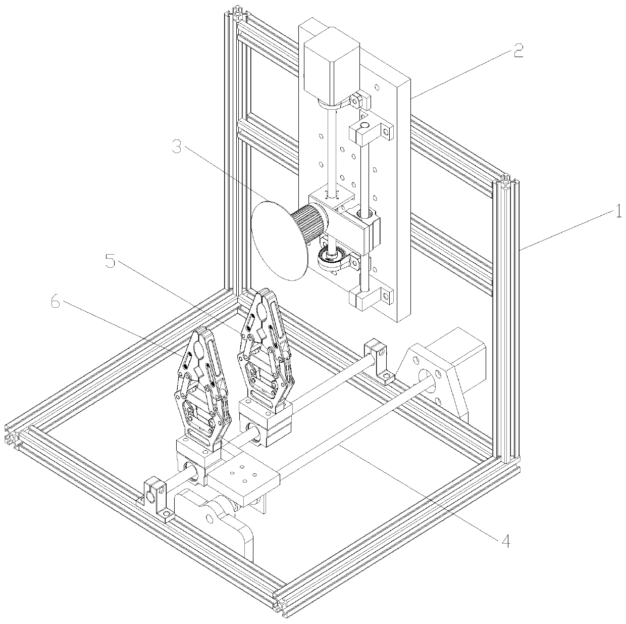
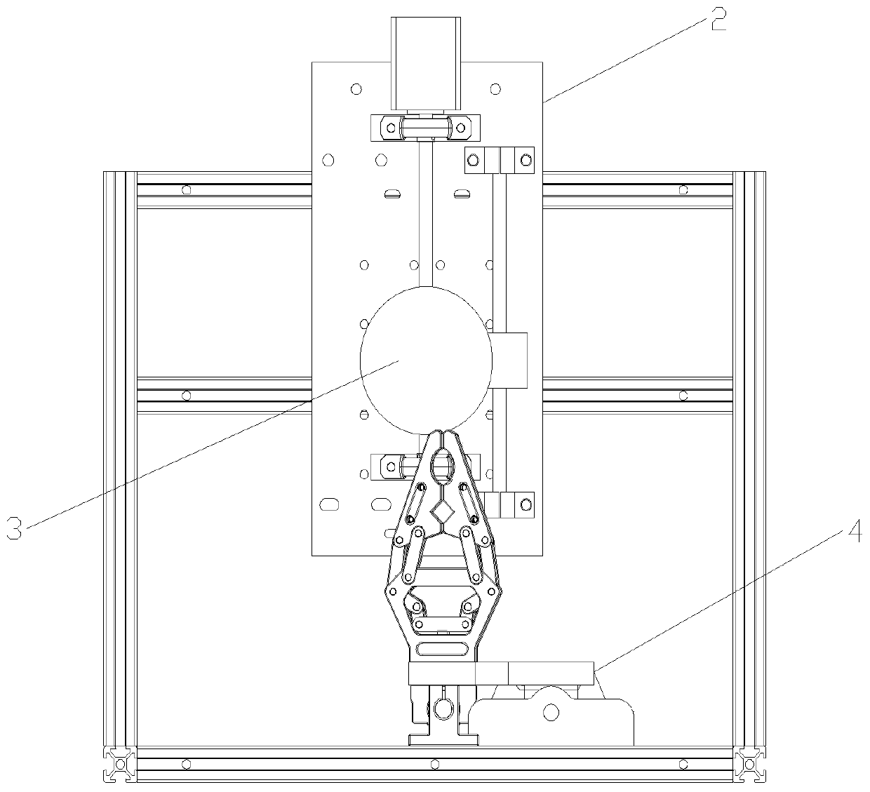
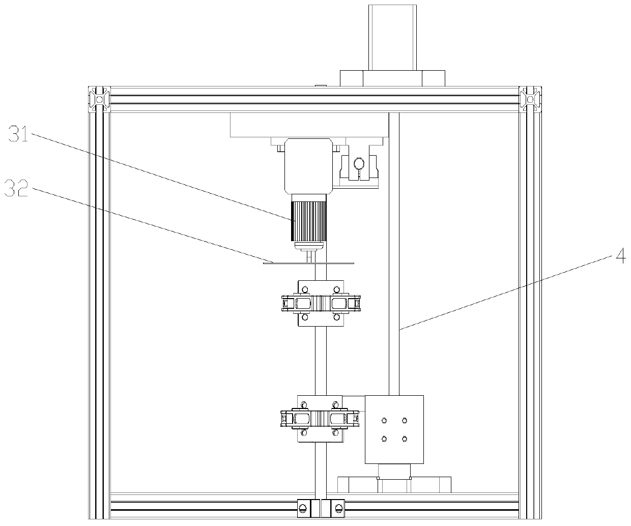
[0037] Such as Figure 1 to Figure 4 As shown, a high-precision aluminum profile cutting device includes a bracket 1, a first moving mechanism 2, a second moving mechanism 3, and a cutting mechanism 3. The first moving mechanism 2 and the second moving mechanism 3 are fixedly connected to the bracket 1. The first moving mechanism 2 is located on the upper side of the second moving mechanism 3. The cutting mechanism 3 is fixedly connected to the first moving mechanism 2, and the second moving mechanism 3 is fixedly connected with a moving clamping mechanism 6 and a fixed clamping mechanism 5. The clamping mechanism 5 is located between the mobile clamping mechanism 6 and the cutting mechanism 3. This solution is provided with a first moving mechanism and a second moving mechanism. The first moving mechanism is used to control the cutting mechanism to move in the vertical direction, and the second moving mechanism is used for To control the moving and clamping mechanism to move in the horizontal direction along the axial direction of the second screw to realize high-precision cutting of aluminum profiles;
[0038] Such as Figure 5 As shown, the first moving mechanism 2 includes a fixed plate 21, a first stepping motor 22, a first screw 23, a first screw seat 24, a first sliding rod 25, a first sliding block 26, a pair of bearings 27 and A pair of fixed seats 28, the first stepping motor 22 is fixedly connected to the fixed plate 21, the output end of the first stepping motor 22 is fixedly connected to the first screw 23, the first screw 23 passes through a pair of bearings 27 Fixedly connected to the fixed plate 21, the first screw seat 24 is connected to the first screw 23, the first sliding rod 25 is fixedly connected to the fixed plate 21 through a pair of fixed seats 28, and the first sliding block 26 is slidably connected to On the first sliding rod 25, a first connecting block 29 is fixedly connected to the first screw seat 24 and the first sliding block 26. The first moving mechanism 2 is used to control the cutting mechanism 3 to move in the vertical direction. The motor 22 is electrically connected to an external power source, the first stepping motor 22 drives the first screw 23 to rotate, and the first screw seat 24 moves on the first screw 23;
[0039] Such as image 3 As shown, the cutting mechanism 3 includes a cutting motor 31 and a cutting blade 32, the cutting blade 32 is fixedly connected to the output end of the cutting motor 31, and the cutting motor 31 is fixedly connected to the first connecting block 29;
[0040] Such as Image 6 As shown, the second moving mechanism 4 includes a second stepping motor 41, a second screw 47, a second screw seat 49, a second sliding rod 44, a second sliding block 46, and a second fixing block 45, on the support 1 The motor base 42 is fixedly connected, the second stepping motor 41 is fixedly connected to the motor base 42, the second screw 47 is fixedly connected to the output end of the second stepping motor 41, and the second screw base 49 is connected to the second On the screw 47, a pair of second fixing seats 43 are fixedly connected to the bracket 1, the second sliding rod 44 is fixedly connected in the second fixing seat 43, the second fixing block 45 is fixedly connected to the second sliding rod 44, The sliding block 46 is slidably connected to the second sliding rod 44, and the second sliding block 46 is located between the second fixing block 45 and the second fixing base 43, and the second sliding block 46 and the second screw base 49 are fixedly connected There is a second connecting block 48. The second moving mechanism 4 is used to control the moving and clamping mechanism 6 to move in the horizontal direction along the axial direction of the second screw 47. The second stepping motor 41 is electrically connected to an external power source. The second step The motor 41 drives the second screw 47 to rotate, the second screw base 49 moves on the second screw 47, and the second screw base 49 drives the second slider 46 to move;
[0041] The fixed clamping mechanism 5 is fixedly connected to the second fixed block 45, the movable clamping mechanism 6 is fixedly connected to the second sliding block 46, and the fixed clamping mechanism 5 is stationary relative to the second sliding rod 44.
[0042] Such as Figure 7 As shown, the mobile clamping mechanism 6 includes a housing 61, a T-shaped connecting rod 62, a pair of first connecting rods 63, a pair of L-shaped connecting rods 65, a pair of H-shaped connecting rods 64, and a pair of clamping heads 66, The T-shaped connecting rod 62 is connected in the housing 61, a pair of first connecting rods 63 are connected to the T-shaped connecting rod 62, a pair of L-shaped connecting rods 65 are connected in the housing 61, and one end of the L-shaped connecting rod 65 is connected On the first connecting rod 63, the other end of the L-shaped connecting rod 65 is connected to the clamping head 66, one end of the H-shaped connecting rod 64 is connected to the casing 61, and the other end of the H-shaped connecting rod 64 is connected to the clamping head. On the head 66, a micro stepping motor is arranged in the housing 61, and the moving end of the micro stepping motor is connected to the T-shaped connecting rod 62. The clamping head 66 is provided with a first groove 67. A second groove 68 is also provided on the clamping head 66. The cross section of the first groove 67 is semicircular, and the cross section of the second groove 68 is triangle. A pair of first grooves 67 clamp the aluminum profile with a circular cross section, and a pair of second grooves 68 clamp the aluminum profile with a rectangular cross section. With this structure, the mobile clamping mechanism 6 and the fixed clamping are improved. The clamping stability of the mechanism 5 improves the precision of processing and cutting and improves the production efficiency. The clamping surface of the clamping head 66 is provided with a non-slip rubber pad, which further improves the clamping stability of the mobile clamping mechanism 6 and the fixed clamping mechanism 5. The structure of the fixed clamping mechanism 5 is the same as that of the mobile clamping mechanism 6.
[0043] The support 1 is composed of stainless steel pipes, and the steel pipe joints of the support 1 are all provided with reinforcement angles, and the reinforcement angles are used to improve the strength of the support 1.
[0044] Such as Figure 8 As shown, the second fixing base 43 includes a T-shaped block 431, a pair of fixing through holes 432 are opened on the T-shaped block 431, a first circular through hole 434 is opened on the T-shaped block 431, and one end of the T-shaped block 431 is opened. A font through hole 435, the inline through hole 435 and the first circular through hole 434 intersect, the T-shaped block 431 is provided with a side through hole 433, the side through hole 433 penetrates the inline through hole 435, and the side through hole A fastening bolt is provided in the 433, and the fastening bolt is tightened to adjust the size of the first circular through hole 434, thereby fixing the second sliding rod 44.
[0045] A method of using high-precision aluminum profile cutting device:
[0046] S1: The first moving mechanism 2 and the second moving mechanism 3 are restored to their initial positions, the cutting motor 31 works, and the cutting motor 31 makes the cutting sheet 32 rotate at a high speed;
[0047] S2: Move the clamping mechanism 6 to open the clamping part, and the fixed clamping mechanism 5 clamps the aluminum profile to be cut;
[0048] S3: Move the clamping mechanism 6 to clamp the aluminum profile to be cut, the fixed clamping mechanism 5 opens the clamping part, the second moving mechanism 3 works, the second stepping motor 41 drives the second slider 46 to move, and the second slider 46 Drive the mobile clamping mechanism 6 to clamp the aluminum profile to be cut to move;
[0049] S4: The first moving mechanism 2 works, the first stepping motor 22 drives the first connecting block 29 to move downwards, the first connecting block 29 drives the cutting mechanism 3 to move downwards, and the cutting blade 32 cuts the aluminum profile;
[0050] S5: After the cutting of the cutting sheet 32 is completed, the first moving mechanism 2 and the second moving mechanism 3 return to the initial positions.
[0051] In the description of this specification, the description with reference to the terms "one embodiment", "example", "specific example", etc. means that the specific feature, structure, material or characteristic described in combination with the embodiment or example is included in at least the present invention. In one embodiment or example. In this specification, the schematic representations of the above terms do not necessarily refer to the same embodiment or example. Moreover, the described specific features, structures, materials or characteristics may be combined in any one or more embodiments or examples in a suitable manner.
[0052] The above shows and describes the basic principles, main features and advantages of the present invention. Those skilled in the industry should understand that the present invention is not limited by the foregoing embodiments. The foregoing embodiments and descriptions only illustrate the principles of the present invention. Without departing from the spirit and scope of the present invention, the present invention may have Various changes and improvements, these changes and improvements fall within the scope of the claimed invention.