Track planning method, track planning device, equipment and storage medium
A trajectory planning and trajectory technology, applied in the field of robotics, can solve the problems of reducer vibration, uneven trajectory transition, and wear, and achieve the effects of reducing wear on the reducer, reducing vibration, and avoiding vibration and wear of the reducer
- Summary
- Abstract
- Description
- Claims
- Application Information
AI Technical Summary
Problems solved by technology
Method used
Image
Examples
Embodiment 1
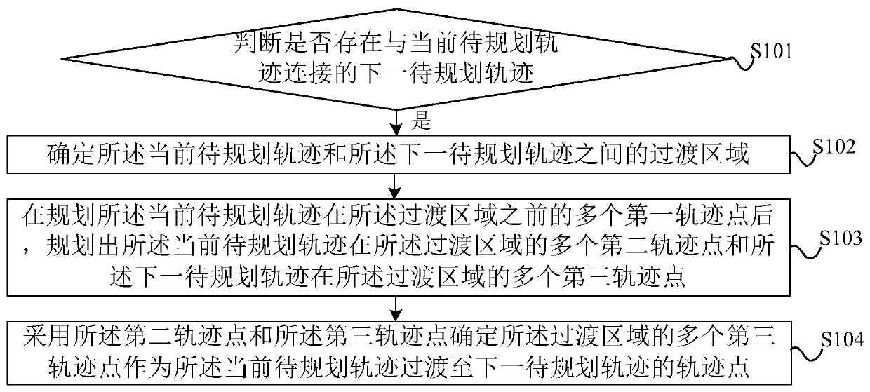
[0035] figure 1 It is a flow chart of a trajectory planning method provided by Embodiment 1 of the present invention. This embodiment is applicable to the situation of planning the motion trajectory of robot joints in space. The trajectory planning method provided in this embodiment can be executed by the trajectory planning device provided in the embodiment of the present invention, and the device can be realized by means of software and / or hardware, and integrated into a device. Specifically, refer to figure 1 , the trajectory planning method of the embodiment of the present invention may include the following steps:
[0036] S101. Determine whether there is a next to-be-planned trajectory connected to the current to-be-planned trajectory.
[0037] In the embodiment of the present invention, the robot may be a general-purpose serial 6-axis robot, a robot with few degrees of freedom, a redundant robot, etc. The trajectory that the robot joints will run in space is the traje...
Embodiment 2
[0051] Figure 3A It is a flowchart of a trajectory planning method provided by Embodiment 2 of the present invention. This embodiment is optimized on the basis of Embodiment 1. Specifically, refer to Figure 3A , the trajectory planning method of the embodiment of the present invention may include the following steps:
[0052] S301. Determine whether to enable the trajectory smoothing mode.
[0053] In the embodiment of the present invention, the smoothing mode may be a mode in which two adjacent trajectories are smoothly connected during the process of planning trajectory points. In practical applications, an option of whether to enable the trajectory smoothing mode may be provided on the interactive interface. When the user selects trajectory smoothing After the mode is activated, the smooth mode is enabled to plan the trajectory, and S303-S311 is executed; otherwise, S302 is executed.
[0054] S302. According to the preset speed curve and the preset speed constraint para...
Embodiment 3
[0148] Figure 5 A schematic structural diagram of a trajectory planning device provided in Embodiment 3 of the present invention, specifically, as Figure 5 As shown, the trajectory planning device in the embodiment of the present invention may include:
[0149] The next trajectory judging module 501 is used to judge whether there is a next trajectory to be planned connected with the current trajectory to be planned;
[0150] Transition area determination module 502, for determining the transition area between the current trajectory to be planned and the next trajectory to be planned;
[0151] The initial trajectory planning module 503 in the transition area, configured to plan a plurality of first trajectory points of the current trajectory to be planned in the transition area after planning the multiple first trajectory points before the transition area. Two trajectory points and a plurality of third trajectory points in the transition region of the next trajectory to be ...
PUM
 Abstract
Description
Claims
Application Information
 - R&D
- Intellectual Property
- Life Sciences
- Materials
- Tech Scout
- Unparalleled Data Quality
- Higher Quality Content
- 60% Fewer Hallucinations
Browse by: Latest US Patents, China's latest patents, Technical Efficacy Thesaurus, Application Domain, Technology Topic, Popular Technical Reports.
© 2025 PatSnap. All rights reserved.Legal|Privacy policy|Modern Slavery Act Transparency Statement|Sitemap|About US| Contact US: help@patsnap.com


