Progressive wooden bead manufacturing device

A production device and progressive technology, which is applied in the field of progressive wooden bead production devices, can solve the problems of cumbersome, slow procedures, and worker injuries, and achieve the effects of simplifying processing procedures, improving processing efficiency, and avoiding injuries

Active Publication Date: 2020-07-10
临沂临港国有资产运营集团有限公司
View PDF9 Cites 5 Cited by
  • Summary
  • Abstract
  • Description
  • Claims
  • Application Information

AI Technical Summary

Problems solved by technology

[0004] In order to overcome the need to hold a cutting knife during manual processing, which may cause injury to workers; during manual processing, it is necessary to continuously cut wood, which is a slow and cumbersome procedure; after manual processing, it is necessary

Method used


Image

  • Progressive wooden bead manufacturing device
  • Progressive wooden bead manufacturing device
  • Progressive wooden bead manufacturing device

Examples


Embodiment 1

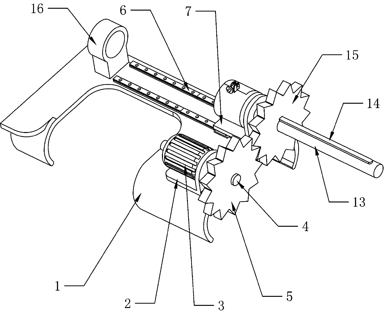
[0023] A progressive wooden bead making device, such as Figure 1-2 As shown, it includes a base plate 1, a motor base 2, a biaxial motor 3, a transmission mechanism and a locking mechanism. The upper side of the right part of the base plate 1 is fixedly connected with a motor base 2, and the upper side of the motor base 2 is installed with a biaxial motor 3. The base plate 1. A transmission mechanism is fixedly connected to the upper side of the right part, and the biaxial motor 3 is connected to the transmission mechanism, and a locking mechanism is fixedly connected to the transmission mechanism.

[0024] Such as Figure 1-2 As shown, the transmission mechanism includes a rotating rod 4, a first gear 5, a linear slide rail 6, a moving seat 7, a rotating shaft 13, a long key bar 14, a second gear 15, a gear mounting seat 151 and a first slideway 16, The output shaft of the biaxial motor 3 is fixedly connected with a rotating rod 4, and the rotating rod 4 is located on the r...

Embodiment 2

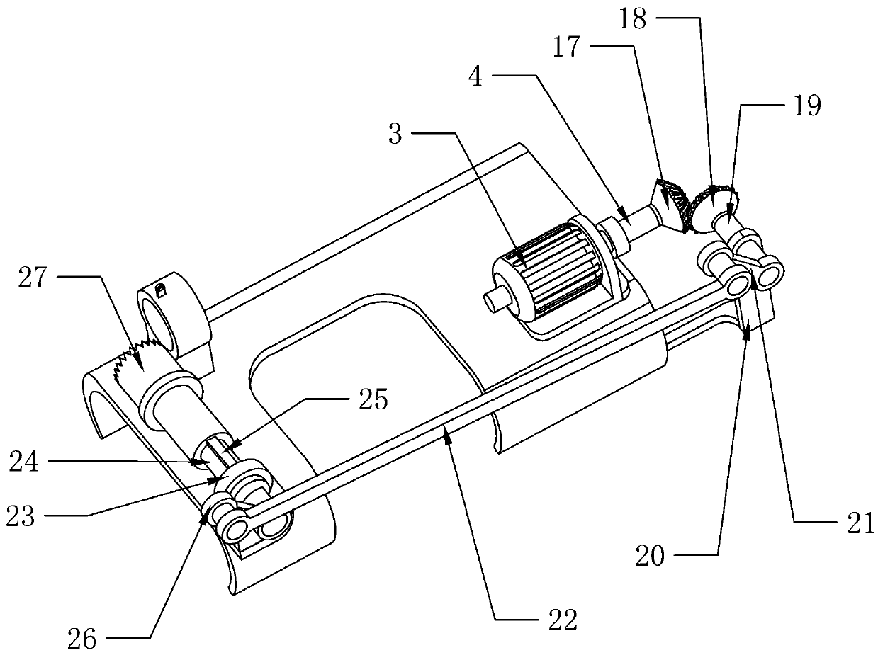
[0030] On the basis of Example 1, such as Figure 4As shown, it also includes a first helical gear 17, a second helical gear 18, a connecting shaft 19, a welding plate 20, a first rocker arm 21, a long rod 22, a bearing seat 23, a sliding shaft 24, a short key bar 25, the first Two rocking arms 26 and cutter 27, the first helical gear 17 is installed on the right end of the rotating rod 4, the front part of the right side of the bottom plate 1 is fixedly connected with a welding plate 20, the upper end of the welding plate 20 is rotatably connected with a connecting shaft 19, and the connecting shaft 19 rear ends The second helical gear 18 is fixedly connected, the front end of the connecting shaft 19 is fixedly connected with the first rocker arm 21, the second helical gear 18 meshes with the first helical gear 17, the front end of the first rocker arm 21 is connected with a long rod 22 for rotation, and the bottom plate 1 A bearing seat 23 is fixedly connected to the upper s...

Embodiment 3

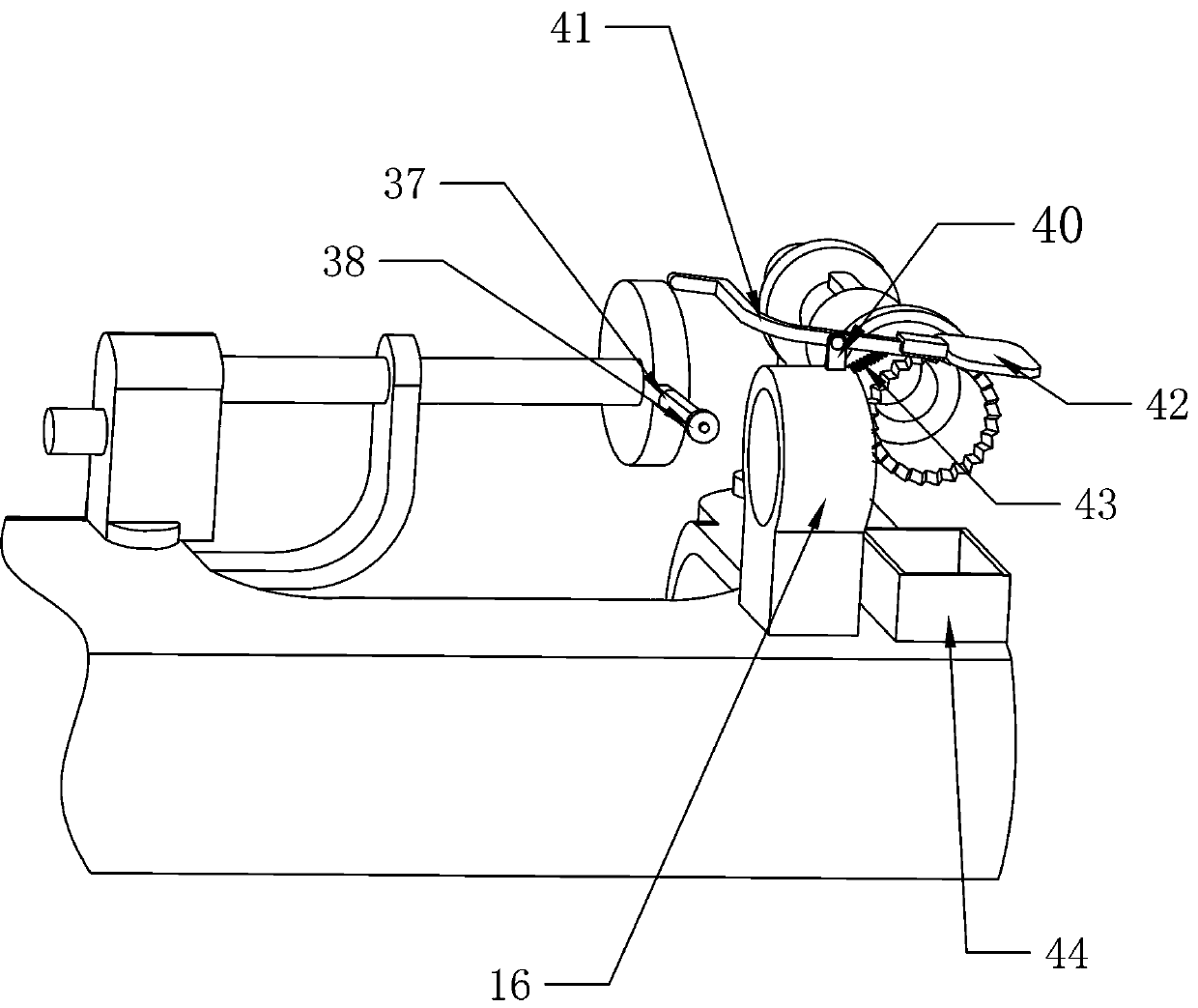
[0033] On the basis of Example 2, such as Figure 5 Shown, also include reducer 28, connecting plate 29, rotating shaft 30, cam 31, offset seat 32, connecting rod 33, second slideway 34, first roller 35 and spring 36, bottom plate 1 right upper side A reducer 28 is fixedly connected, the output shaft on the left side of the biaxial motor 3 is fixedly connected to the input shaft of the reducer 28, the lower side of the bottom plate 1 is fixedly connected with a connecting plate 29, and the upper part of the connecting plate 29 is pierced with a rotating shaft 30, and the rotating shaft 30 is connected to the The bottom plate 1 is parallel, the right end of the rotating shaft 30 is fixedly connected to the output shaft of the reducer 28, the left end of the rotating shaft 30 is fixedly connected with a cam 31, the middle part of the cutting knife 27 is provided with an offset seat 32 through a bearing sleeve, and the right side of the offset seat 32 is fixedly connected with a ...


PUM


Abstract

The invention relates to a manufacturing device, in particular to a progressive wooden bead manufacturing device. The technical problem of the progressive wooden bead manufacturing device is how to provide a progressive wooden bead manufacturing device which can automatically cut wood and further automatically beat a cut wood ball down. The progressive wooden bead manufacturing device comprises abottom plate, a transmission mechanism and a locking mechanism, wherein a motor seat is fixedly connected to the bottom plate, and a biaxial motor is mounted on the motor seat; the transmission mechanism is fixedly connected to the bottom plate, and the biaxial motor is connected to the transmission mechanism; and the locking mechanism is fixedly connected to the transmission mechanism. The progressive wooden bead manufacturing device is driven by the motor, can automatically rotate a wooden cylinder, the motor drives a cutting knife to rotate, automatic cutting of the wooden cylinder is realized, the tedious processing procedure is simplified, and no using the hand-held cutting knife is further required.

Description

technical field [0001] The invention relates to a production device, in particular to a progressive wooden bead production device. Background technique [0002] Buddha beads are portable tools used by Buddhists to recite and count, and are widely used among monks and laymen. The original name "rosary beads" originated from the name of the Three Jewels of the Buddha, the Dharma, and the monks, and is used to eliminate troubles and obstacles. Generally, it can be divided into three types: holding beads, wearing beads and hanging beads. The number of beads in each string represents different meanings. The quality of Buddhist beads is too numerous to enumerate, and those made of "Seven Treasures" are the most noble. Bodhi seeds are the most well-known type of beads. Now people prefer to wear bracelets as decorations, and bracelets are made of wooden beads threaded. When obtaining wooden beads, wood needs to be processed. At present, wooden beads are obtained by artificially ...

Claims


Application Information

Patent Timeline
IPC IPC(8): B27C5/08
CPCB27C5/08Y02P40/57
Inventor 杨明凤
Owner 临沂临港国有资产运营集团有限公司
Why Eureka
Try Eureka