Energy conversion device and vehicle

A technology of an energy conversion device and a vehicle, which is applied in the field of vehicles and can solve problems such as the inability to coordinate the motor drive process and the like.

Active Publication Date: 2020-07-10
BYD CO LTD
View PDF10 Cites 9 Cited by
  • Summary
  • Abstract
  • Description
  • Claims
  • Application Information

AI Technical Summary

Problems solved by technology

[0003] However, the heating process of the battery pack in the prior art cannot be coordinated with the motor driving process. Therefore, there is an urgent need for a technical solution that enables the coordinated realization of the driving function and the heating function.

Method used


Image

  • Energy conversion device and vehicle
  • Energy conversion device and vehicle
  • Energy conversion device and vehicle

Examples


Embodiment approach

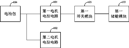
[0048] As an implementation, the first battery pack heating circuit includes a discharge energy storage stage, a discharge energy release stage, a charge energy storage stage, and a charge release energy stage; when the first battery pack heating circuit is in the discharge energy storage stage, the battery pack 104 , the first motor inverter, the first motor winding, the first switch module 105, and the first energy storage module 103 form a discharge energy storage circuit;

[0049] When the heating circuit of the first battery pack is in the discharge energy release stage, the first motor winding, the first switch module 105, the first energy storage module 103, and the first motor inverter form a discharge energy release circuit;

[0050] When the heating circuit is in the charging and energy storage stage, the first energy storage module 103, the first switch module 105, the first motor winding, and the first motor inverter form a charging and energy storage circuit;

[0...


PUM


Abstract

The technical scheme of the invention provides an energy conversion device and a vehicle. The energy conversion device comprises a first motor electric control circuit, a second motor electric controlcircuit and a controller. When the controller is configured to operate in a first control mode, the controller controls a first motor inverter in the first motor electric control circuit, so that a battery pack, a first motor inverter and a first motor winding form a first battery pack heating circuit; an internal resistor of the battery pack is heated through the first battery pack heating circuit; meanwhile, a second motor inverter in the second motor electric control circuit is controlled to output power; heating and driving of the energy conversion device are carried out at the same time,due to the fact that the first motor electric control circuit is adopted for heating and the second motor electric control circuit is adopted for driving, excessive loss of the motor winding and themotor inverter in the motor driving circuit is avoided, and the service life of devices in the circuit is prolonged.

Description

technical field [0001] The present application relates to the technical field of vehicles, in particular to an energy conversion device and a vehicle. Background technique [0002] With the widespread use of new energy sources, battery packs can be used as power sources in various fields. Depending on the environment in which the battery pack is used as a power source, the performance of the battery pack will also be affected. For example, the performance of a battery pack in a low temperature environment will be reduced to a greater extent than that at normal temperature. For example, at zero temperature, the discharge capacity of the battery pack will decrease as the temperature decreases. Under the condition of -30°C, the discharge capacity of the battery pack is basically 0, making the battery pack unusable. In order to be able to use the battery pack in a low temperature environment, it is necessary to preheat the battery pack before using it. [0003] However, the ...

Claims


Application Information

Patent Timeline
Patent Type & Authority Applications(China)
IPC IPC(8): B60L58/27B60L53/24B60L15/20H01M10/615H01M10/625H01M10/667
CPCB60L58/27B60L53/24B60L15/20H01M10/615H01M10/625H01M10/667H01M2220/20Y02T10/70Y02T10/7072Y02T90/14Y02E60/10Y02T10/72B60L1/003B60L2240/423H01M10/637Y02T10/92H02P29/68H02P27/06
Inventor 凌和平闫磊熊永洪臣张俊伟
Owner BYD CO LTD
Why Eureka
Try Eureka