Lifting device for turning bearing rings

A bearing ring, turning processing technology, applied in the field of bearing processing, can solve the problems of wear or pollution of the side wall of the bearing ring, reduce the bearing rotation performance, and affect the surface integrity of the bearing ring, so as to ensure the integrity, guarantee The effect of production quality

Active Publication Date: 2020-07-10
SHANDONG YUJIE BEARING MFG CO LTD
View PDF8 Cites 2 Cited by
  • Summary
  • Abstract
  • Description
  • Claims
  • Application Information

AI Technical Summary

Problems solved by technology

[0002] The processing of bearings is generally produced in an assembly line, which can greatly improve the efficiency of production and processing. The production of an assembly line involves a flow system composed of multiple processing equipment. Because the models of different equipment are different, so according to the equipment itself and the installation environment. Different, each The height of the feed inlet of the equipment is different, so a lifting device is needed to connect the bearing rings between different equipments to ensure that the bearing rings can smoothly flow between the various equipments, but now Some lifting devices generally place the bearing ring on the lifting plate. During the lifting process, the side wall of the bearing ring will always be in contact with the inner side wall where the discharge port of the casing is located. During the lifting process, the bearing The ring is constantly moving relative to the side wall of the casing, so relative friction will be generated, which will cause wear or contamination of the side wall of the bearing ring, which will affect the surface integrity of the processed bearing ring and eventually reduce The rotation performance of the bearing is affected, which affects the quality of bearing production

Method used


Image

  • Lifting device for turning bearing rings
  • Lifting device for turning bearing rings
  • Lifting device for turning bearing rings

Examples


Embodiment Construction

[0019] Below in conjunction with specific embodiment, further illustrate the present invention. It should be understood that these examples are only used to illustrate the present invention and are not intended to limit the scope of the present invention. In addition, it should be understood that after reading the content taught by the present invention, those skilled in the art may make various changes or modifications to the present invention, and these equivalent forms also fall within the scope defined in the present application.

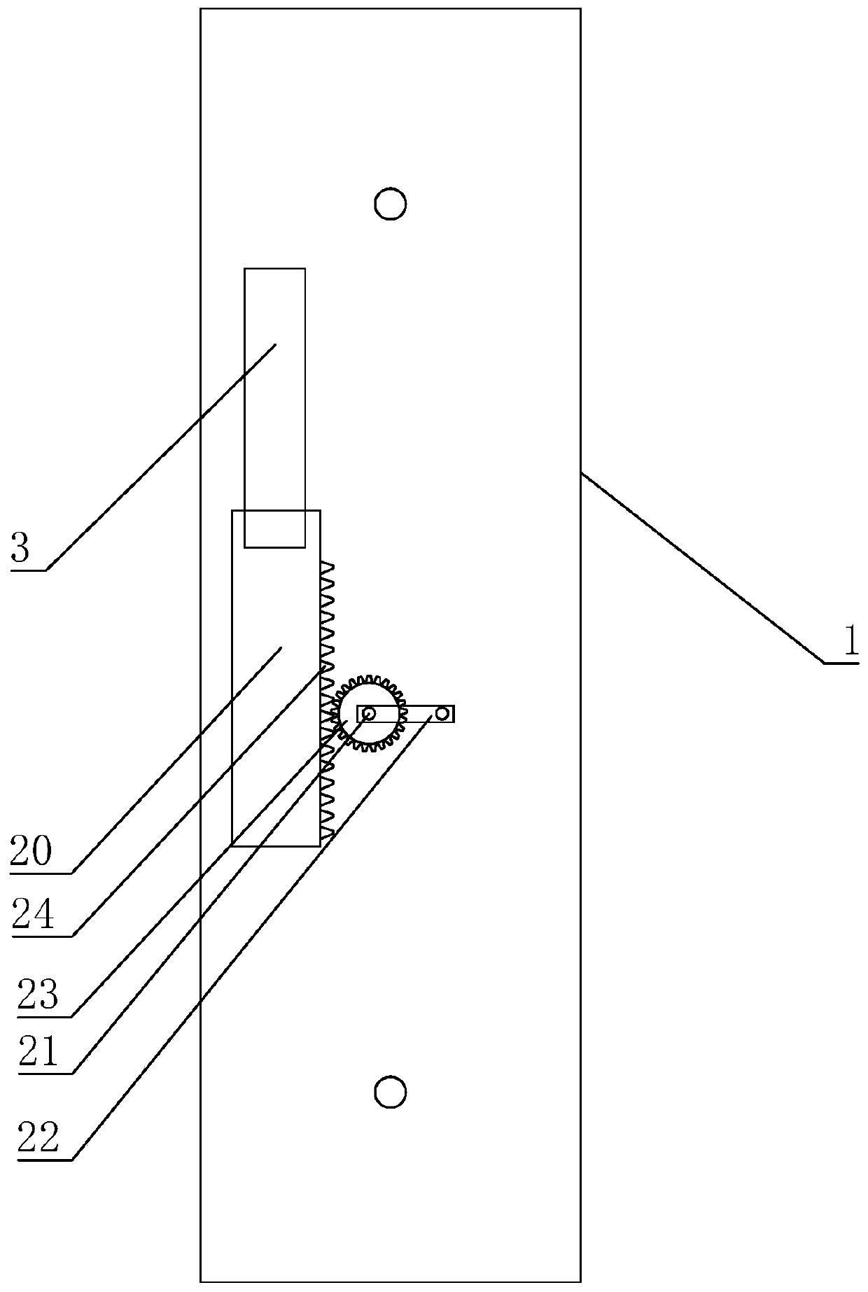
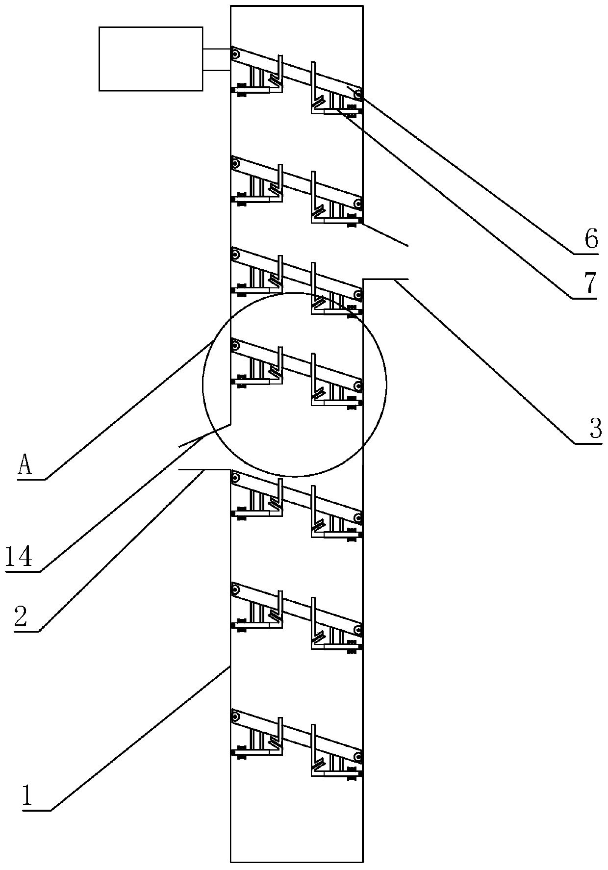
[0020] The present invention is a hoisting device for bearing ring turning. The main structure includes a casing 1. The bottom of the casing 1 is fixed on the ground by bolts. The casing 1 is arranged on two adjacent processing Between the equipment, the casing 1 is provided with a feed port 2 and a discharge port 3, the height of the discharge port 3 is generally higher than the feed port 2, and the feed port 2 is the same as the previous equip...


PUM


Abstract

The invention discloses a lifting device for turning bearing rings, and mainly relates to the field of bearing machining. The lifting device comprises a shell, wherein a feeding port and a dischargingport are formed in the shell; two rollers are rotatably connected to the inside of the shell; a belt is connected between the two rollers; and a plurality of lifting plates are arranged on the belt.The lifting device is characterized in that the ends, facing the discharging port, of the lifting plates are inclined downwards; bearing temporarily storing devices are arranged on the lifting platesand comprise through holes; a baffle is slidably connected inside each through hole along the height direction; a first inclined plate is arranged at the bottom of each baffle; a sleeve pipe is arranged at the bottom of each lifting plate; a moving column is horizontally connected to the inside of each sleeve pipe in a sliding mode; a second inclined plate is arranged at one end, close to the corresponding baffle, of each moving column; and inclined retracting plates are respectively arranged above the feeding port and the discharging port. The lifting device for turning the bearing rings hasthe beneficial effects that it can be ensured that bearings do not relatively rub against the side wall of the shell in the lifting process of the bearing rings, so that quality of the machined bearings is guaranteed.

Description

technical field [0001] The invention relates to the field of bearing processing, in particular to a lifting device for processing bearing rings. Background technique [0002] The processing of bearings is generally produced in an assembly line, which can greatly improve the efficiency of production and processing. The production of an assembly line involves a flow system composed of multiple processing equipment. Because the models of different equipment are different, so according to the equipment itself and the installation environment. Different, each The height of the feed inlet of the equipment is different, so a lifting device is needed to connect the bearing rings between different equipments to ensure that the bearing rings can smoothly flow between the various equipments, but now Some lifting devices generally place the bearing ring on the lifting plate. During the lifting process, the side wall of the bearing ring will always be in contact with the inner side wall ...

Claims


Application Information

Patent Timeline
Patent Type & Authority Applications(China)
IPC IPC(8): B65G23/04B65G15/58B65G47/38
CPCB65G15/58B65G23/04B65G47/38
Inventor 蔡玉铨陈明星王松盛成伟李之立张庆霄
Owner SHANDONG YUJIE BEARING MFG CO LTD
Why Eureka
Try Eureka