Method for directional dumping demolition of blast furnace body

A technology of blast furnace and body, which is applied in the field of directional dumping and demolition of blast furnace body, which can solve the problems of high safety risk, long time, corrosion of steel structure, etc., and achieve the effect of reducing construction workload, shortening demolition time and ensuring safety

Inactive Publication Date: 2020-07-10
MAANSHAN IRON & STEEL CO LTD
View PDF3 Cites 1 Cited by
  • Summary
  • Abstract
  • Description
  • Claims
  • Application Information

AI Technical Summary

Problems solved by technology

[0003] The blast furnace needs to be dismantled after the permanent shutdown. However, several related blast furnaces are shut down at different time intervals, with an interval of more than 2 years. Due to the sharing of power, supply and auxiliary systems, and gas pipeline network, only effective cutoff of gas can be carried out. Shutdown blast furnace cannot be dismantled first
With the passage of time, the steel structure of the stopped blast furnace body has been severely corroded, and the cl

Method used


Image

  • Method for directional dumping demolition of blast furnace body

Examples


Example Embodiment

[0021] Example one

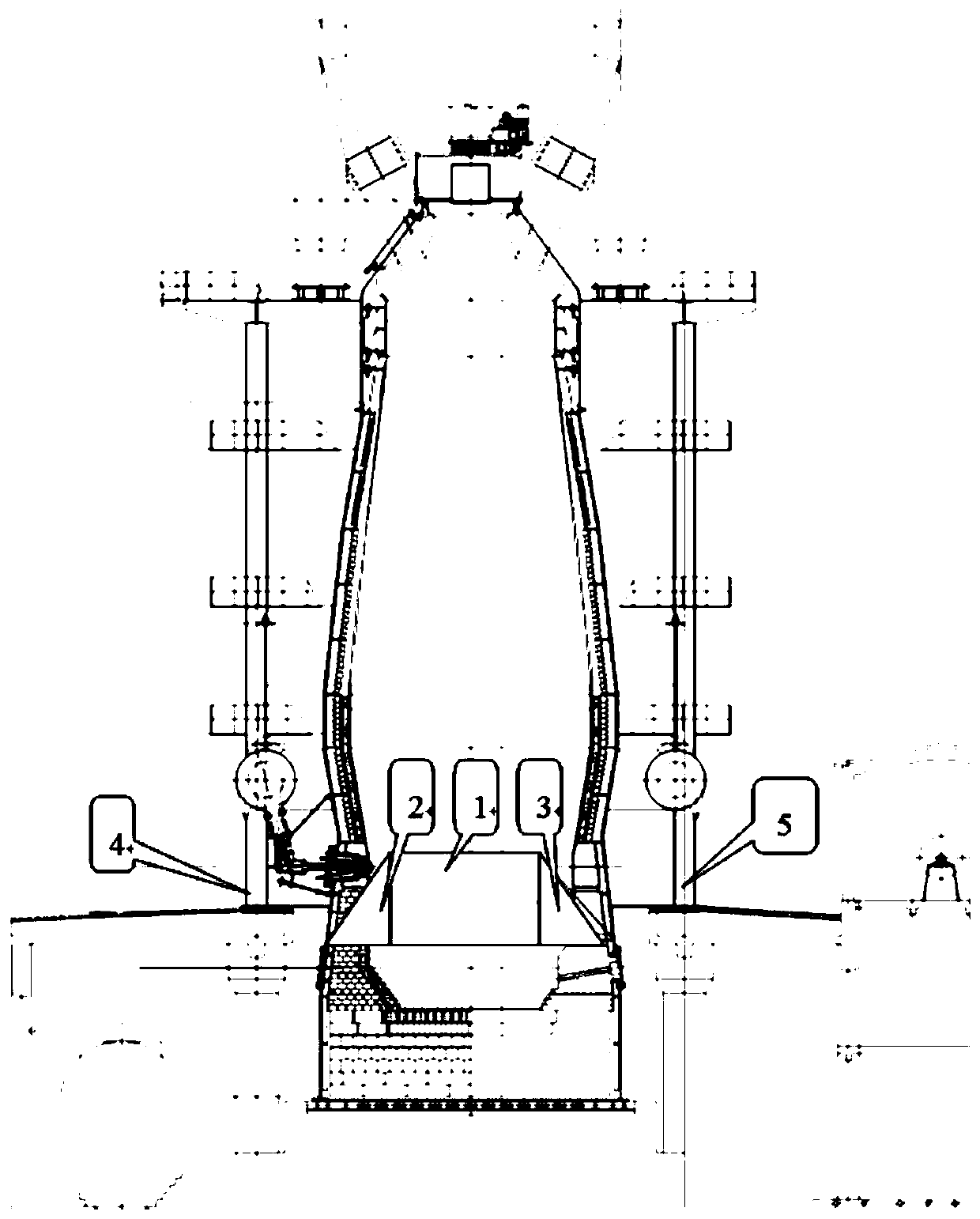
[0022] See figure 1 , A method for directional dumping and dismantling of a blast furnace body includes the following steps:

[0023] 1) Dismantle the blast furnace body's hot air enclosure, gas gravity dust collector, washing tower and pipes, electromagnetic station, hoisting room and diagonal bridge in advance to isolate the blast furnace steel structure;

[0024] 2) Design high body furnace shell, cold plate, steel structure cutting, cleaning, and column cutting plan;

[0025] 3) Set up damping ditch and damping pad for dumping of blast furnace body;

[0026] 4) Break the blast furnace frame column by disintegrating and hitting the blast furnace with the help of a crusher;

[0027] 5) After the frame is dumped, the blast furnace body is pulled for directional dumping, and the steel structure is disassembled and transported on the ground.

[0028] Directional dumping method of blast furnace

[0029] Including the scope of the dismantled blast furnace hearth to the t...

Example Embodiment

[0048] Example two

[0049] Step 1: Before dismantling the main body of the blast furnace, dismantle the equipment and facilities around the main body in advance. The dismantling content includes the gas downpipe, gravity dust collector, washing tower and other gas dust removal systems; hot air enclosure and chimney, feeding system hoisting room, Electromagnetic station and diagonal bridge (or belt corridor) isolate the blast furnace body.

[0050] Step 2: Clean up the site around the blast furnace body.

[0051] Step 3: Soil layer stacking:

[0052] (1) Fill the blast furnace to a height of about +3m from the concrete base of the furnace body, make a slope and compact it to facilitate the construction of the mechanical station and the evacuation of personnel.

[0053] (2) Check the construction site. If it is not level or compact, it should be filled and compacted to ensure that the site is open and the emergency passage is free of obstructions, so that in case of emergency, the const...


PUM

PropertyMeasurementUnit
Tensile strengthaaaaaaaaaa

Abstract

The invention discloses a method for directional dumping demolition of a blast furnace body. The blast furnace steel structure body is isolated by dismantling a blast furnace body bustle pipe, a coalgas gravity dust remover, a washing tower, a pipeline, an electromagnetic station, a winch room, a skew bridge and the like in advance. A scheme of cutting and cleaning a part of a furnace shell of the body, a cold plate and a steel structure and cutting stand columns is designed, damping ditches and shock pads for dumping the blast furnace body are arranged, disassembling and striking are conducted with the help of an extension arm crusher, the stand columns of a frame of a blast furnace are fractured, after the frame is dumped, the blast furnace body is pulled for directional dumping, then disassembling and transportation of the steel structure and the like are carried out on the ground, and the blast furnace steel structure body is dismantled safely, quickly, conveniently and economically.

Description

technical field [0001] The invention belongs to equipment dismantling of a blast furnace body, and in particular relates to a method for directional dumping and dismantling of a blast furnace body. Background technique [0002] In the process of realizing the present invention, the inventor finds that there are at least the following problems in the prior art: [0003] The blast furnace needs to be dismantled after the permanent shutdown. However, several associated blast furnaces are shut down at different times, with an interval of more than 2 years. Due to the sharing of power, supply and auxiliary systems, and gas pipeline network, only effective cutoff of gas can be carried out. The blast furnace that has been stopped cannot be dismantled first. With the passage of time, the steel structure of the shut-down blast furnace was severely corroded, and the closed ladders, guardrails, and platforms could not be opened normally. [0004] During normal dismantling, it is firs...

Claims


Application Information

Patent Timeline
IPC IPC(8): C21B7/00
CPCC21B7/00
Inventor 程静波陈义信郑泽宇尹炳富
Owner MAANSHAN IRON & STEEL CO LTD
Why Eureka
Try Eureka