An anti-uplift U-shaped subgrade structure and its design method
A design method and subgrade technology, applied in the field of geotechnical engineering, can solve problems such as increased land use, many uncertain factors in pile group foundation design, and damage to the ecological environment
- Summary
- Abstract
- Description
- Claims
- Application Information
AI Technical Summary
Problems solved by technology
Method used
Image
Examples
Embodiment 1
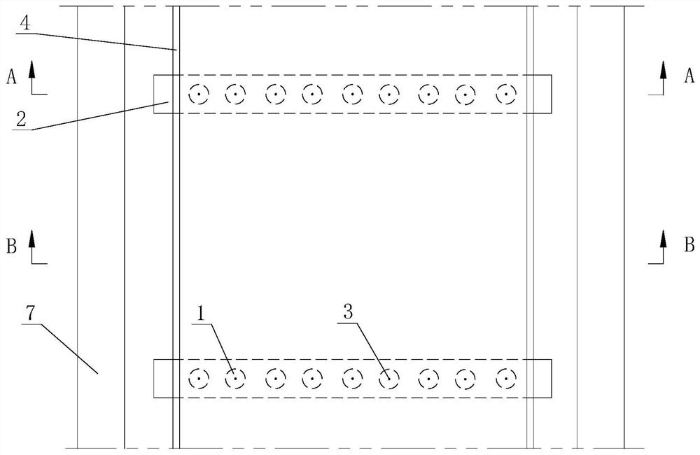
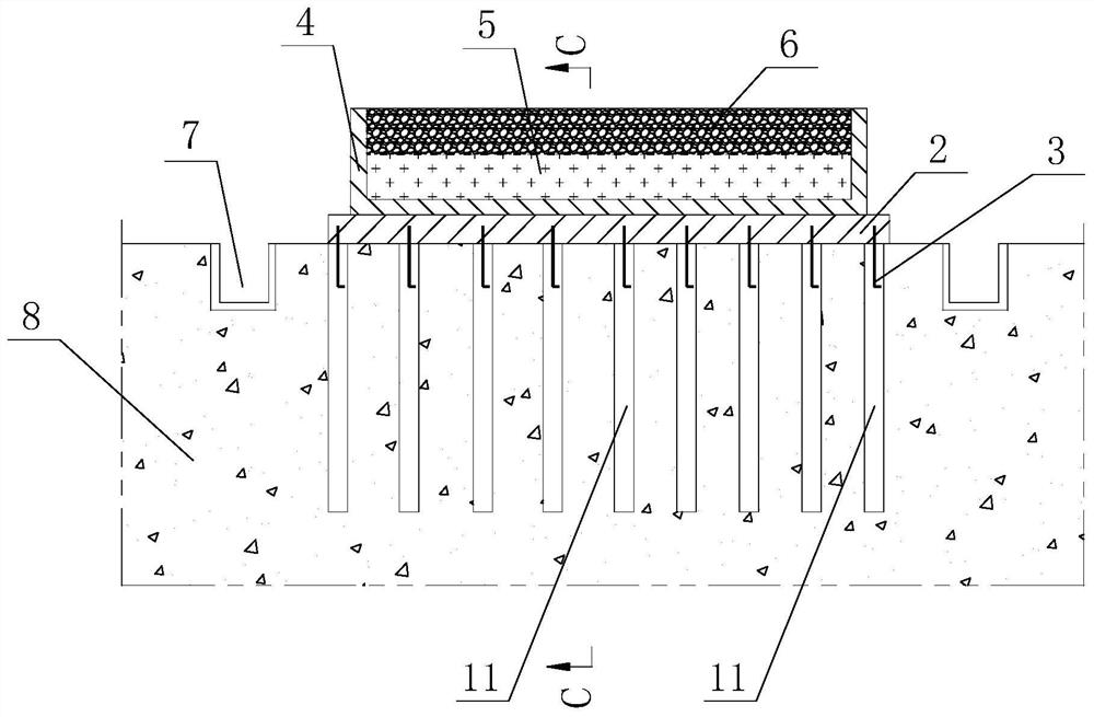
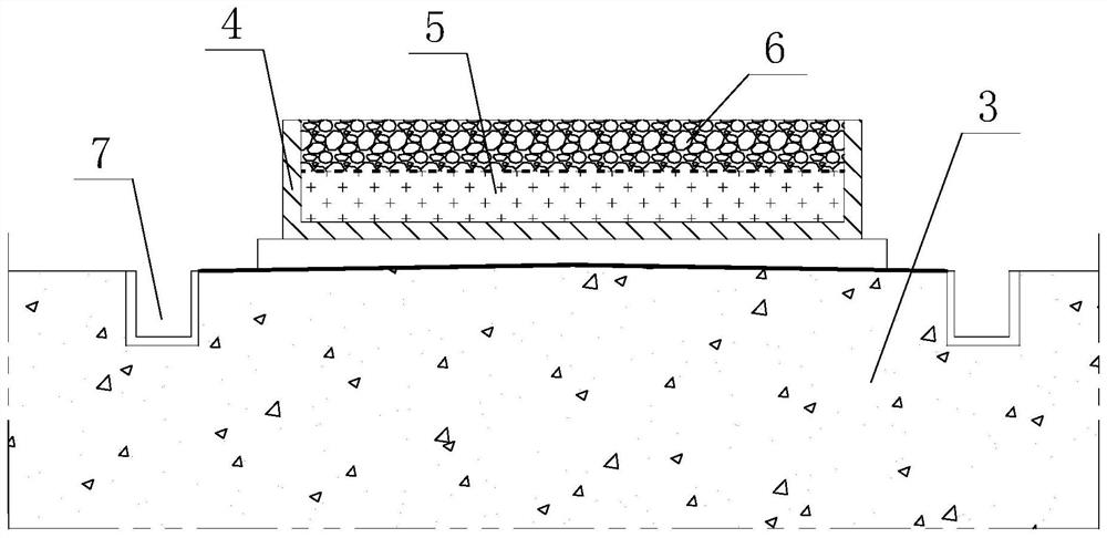
[0073] Such as Figure 1-4 As shown, an anti-uplift U-shaped subgrade structure includes a U-shaped trough 4 with an open top, and a plurality of support beams 2 for supporting the U-shaped trough 4 are arranged at the bottom of the U-shaped trough 4 , all the support beams 2 are arranged at intervals along the length direction of the U-shaped groove body 4, the bottom of the support beams 2 is connected with a reinforcement pile assembly 1, and the reinforcement pile assembly 1 includes several reinforcement piles 11, all of the reinforcement piles The piles 11 are arranged at intervals along the length direction of the support beam 2, and the first filling layer 5 and the second filling layer 6 are sequentially arranged in the U-shaped groove body 4 from top to bottom, and the first filling layer 5 is made of earth material The second filling layer 6 is filled with light soil.
[0074] An anti-uplift U-shaped subgrade structure according to the present invention, the U-shap...
Embodiment 2
[0087] Such as Figure 1-4 As shown, a roadbed structure described in this embodiment includes a foundation 8 and the anti-uplift U-shaped roadbed structure as described in Embodiment 1, the reinforcement pile 11 is arranged in the foundation 8, and the support beam 2 Set on the foundation 8 , there is a gap between the U-shaped groove body 4 between the adjacent support beams 2 and the foundation 8 .
[0088] In the subgrade structure described in this application, the support beam 2 is arranged on the foundation 8, which can be used to transfer the load of the U-shaped groove body 4 to the foundation 8 and the reinforcement pile 11, and will act on the bottom of the support beam 2 The uplift force of the ground is transmitted to the reinforcement pile 11, and there is a gap between the U-shaped groove body 4 between the adjacent support beams 2 and the foundation 8, thereby preventing the uplift force of the foundation 8 from directly acting on the U-shaped groove bottom. ...
Embodiment 3
[0093] Such as Figure 1-5 As shown, a design method for the subgrade structure includes the following steps:
[0094] ①Determine the structural weight W of the support beam 2 by the following formula z :
[0095] W z =BLHγ c
[0096] where W z is the structural weight of the support beam 2, in kN; B is the width of the support beam 2, in m; L is the length of the support beam 2, in m; H is the height of the support beam 2, in m; c is the weight of reinforced concrete, in kN / m 3 ;
[0097] ②Determine the structural weight W of the U-shaped tank body 4 by the following formula u :
[0098] W u =(bh 1 +2hh 2 )Sγ c
[0099] where W u is the structural weight of the U-shaped tank 4, in kN; b is the width of the U-shaped tank 4, in m; h 1 is the thickness of the bottom plate of the U-shaped tank 4, in m; h is the height of the U-shaped tank 4, in m; h 2 is the cantilever thickness of the U-shaped trough 4, in m; S is the distance between the longitudinal support be...
PUM
 Abstract
Description
Claims
Application Information
 - R&D
- Intellectual Property
- Life Sciences
- Materials
- Tech Scout
- Unparalleled Data Quality
- Higher Quality Content
- 60% Fewer Hallucinations
Browse by: Latest US Patents, China's latest patents, Technical Efficacy Thesaurus, Application Domain, Technology Topic, Popular Technical Reports.
© 2025 PatSnap. All rights reserved.Legal|Privacy policy|Modern Slavery Act Transparency Statement|Sitemap|About US| Contact US: help@patsnap.com


