Anti-rise U-shaped roadbed structure and design method thereof

A design method and subgrade technology, applied in the field of geotechnical engineering, can solve problems such as many uncertain factors in pile group foundation design, increased investment in pile-slab structure engineering, and damage to the ecological environment, so as to achieve energy-saving and low-carbon design concepts, reduce ecological Environmental damage and the effect of saving construction land

Active Publication Date: 2020-07-10
CHINA RAILWAY ERYUAN ENG GRP CO LTD
View PDF7 Cites 1 Cited by
  • Summary
  • Abstract
  • Description
  • Claims
  • Application Information

AI Technical Summary

Problems solved by technology

[0007] The purpose of the present invention is: in view of the prior art, the excavation and replacement for anti-uplift deformation seriously damages the ecological environment; the investment in pile-slab structure engineering increases sharply; there are many uncertain factors in the design of pile group foundations, and the embankment slope is obvious To solve the problem of increasing land use, provide an anti-uplift U-shaped subgrade structure and its design method, which can not only effectively control subgrade uplift deformation, but also effectively bear the overall load of the structure and control settlement deformation; save construction land and reduce ecological environment damage

Method used


Image

  • Anti-rise U-shaped roadbed structure and design method thereof
  • Anti-rise U-shaped roadbed structure and design method thereof
  • Anti-rise U-shaped roadbed structure and design method thereof

Examples


Embodiment 1

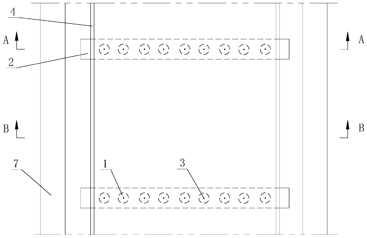
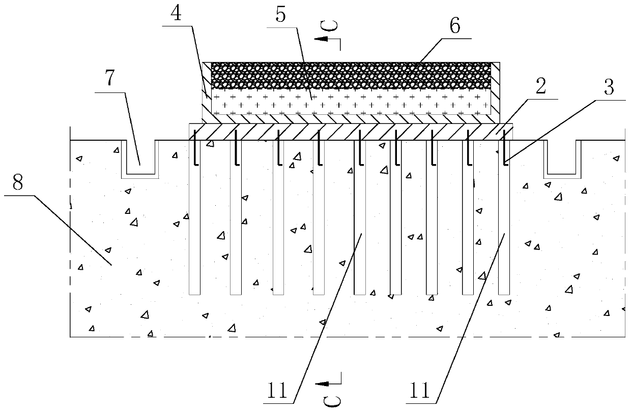
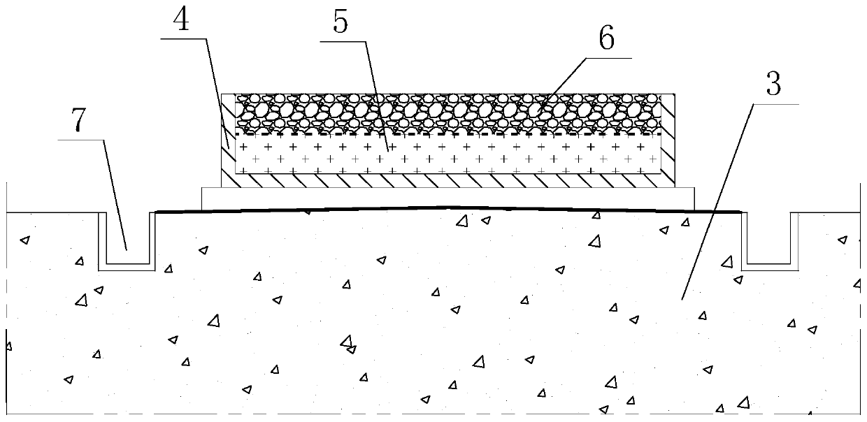
[0073] Such as Figure 1-4 As shown, an anti-uplift U-shaped subgrade structure includes a U-shaped trough 4 with an open top, and a plurality of support beams 2 for supporting the U-shaped trough 4 are arranged at the bottom of the U-shaped trough 4 , all the support beams 2 are arranged at intervals along the length direction of the U-shaped groove body 4, the bottom of the support beams 2 is connected with a reinforcement pile assembly 1, and the reinforcement pile assembly 1 includes several reinforcement piles 11, all of the reinforcement piles The piles 11 are arranged at intervals along the length direction of the support beam 2, and the first filling layer 5 and the second filling layer 6 are sequentially arranged in the U-shaped groove body 4 from top to bottom, and the first filling layer 5 is made of earth material The second filling layer 6 is filled with light soil.

[0074] An anti-uplift U-shaped subgrade structure according to the present invention, the U-shap...

Embodiment 2

[0087] Such as Figure 1-4 As shown, a roadbed structure described in this embodiment includes a foundation 8 and the anti-uplift U-shaped roadbed structure as described in Embodiment 1, the reinforcement pile 11 is arranged in the foundation 8, and the support beam 2 Set on the foundation 8 , there is a gap between the U-shaped groove body 4 between the adjacent support beams 2 and the foundation 8 .

[0088] In the subgrade structure described in this application, the support beam 2 is arranged on the foundation 8, which can be used to transfer the load of the U-shaped groove body 4 to the foundation 8 and the reinforcement pile 11, and will act on the bottom of the support beam 2 The uplift force of the ground is transmitted to the reinforcement pile 11, and there is a gap between the U-shaped groove body 4 between the adjacent support beams 2 and the foundation 8, thereby preventing the uplift force of the foundation 8 from directly acting on the U-shaped groove bottom. ...

Embodiment 3

[0093] Such as Figure 1-5 As shown, a design method for the subgrade structure includes the following steps:

[0094] ①Determine the structural weight W of the support beam 2 by the following formula z :

[0095] W z =BLHγ c

[0096] where W z is the structural weight of the support beam 2, in kN; B is the width of the support beam 2, in m; L is the length of the support beam 2, in m; H is the height of the support beam 2, in m; c is the weight of reinforced concrete, in kN / m 3 ;

[0097] ②Determine the structural weight W of the U-shaped tank body 4 by the following formula u :

[0098] W u =(bh 1 +2hh 2 )Sγ c

[0099] where W u is the structural weight of the U-shaped tank 4, in kN; b is the width of the U-shaped tank 4, in m; h 1 is the thickness of the bottom plate of the U-shaped tank 4, in m; h is the height of the U-shaped tank 4, in m; h 2 is the cantilever thickness of the U-shaped trough 4, in m; S is the distance between the longitudinal support be...


PUM


Abstract

The invention relates to the field of geotechnical engineering, in particular to an anti-rise U-shaped roadbed structure and a design method thereof. The anti-rise U-shaped roadbed structure comprisesa U-shaped groove body, wherein a plurality of supporting beams are arranged at the bottom of the U-shaped groove body. Reinforcing pile assemblies are connected to the bottoms of the supporting beams; each reinforcing pile assembly comprises a plurality of reinforcing piles, a first filling layer and a second filling layer are sequentially arranged in the U-shaped groove body from top to bottom,the first filling layer is formed by filling soil materials, and the second filling layer is formed by filling light soil. According to the anti-rise U-shaped roadbed structure, the upper load of thereinforcing pile assembly is reduced; most rise acting force on the side wall of the reinforcing pile can be transmitted back to a lower foundation through the anchoring effect of the pile body, so that roadbed rise deformation can be effectively controlled, the overall load of the structure can be effectively borne, and sedimentation deformation is controlled; and the construction land is greatly saved, the land is saved, and the damage to the ecological environment is reduced.

Description

technical field [0001] The invention relates to the field of geotechnical engineering, in particular to an anti-uplift U-shaped subgrade structure and a design method thereof. Background technique [0002] In the field of high-speed railway embankment (especially low embankment or cutting bed) and tunnel engineering, the uplift deformation of rock foundation is a key problem to be solved in many projects nowadays, such as frost heave of permafrost, expansive rock (soil) expansion, red Arching of soft rock, salt expansion of saline soil (rock) and other factors are new problems faced by railway builders. This is related to the extremely strict requirements for deformation control of high-speed ballastless railways. If the deformation of the foundation uplift exceeds the limit, it will easily lead to the cracking of the ballastless track slab of the high-speed railway, causing major ballastless track defects, affecting the smooth and comfortable operation of the train, and may...

Claims


Application Information

Patent Timeline
Patent Type & Authority Applications(China)
IPC IPC(8): E01B2/00E02D5/22E03F5/04G06F30/13G06F30/20G06F119/14
CPCE01B2/006E02D5/22E03F5/04
Inventor 陈伟志蒋关鲁姚裕春叶世斌孙晓
Owner CHINA RAILWAY ERYUAN ENG GRP CO LTD
Why Eureka
Try Eureka