Floor knocking device and floor mounting robot with same

A floor and installation groove technology, applied in the field of floor installation robots and floor knocking devices, can solve the problems of easily damaging the floor and affecting the installation effect of the floor, and achieve the effect of improving the installation effect, good practicability and reducing the gap.

Active Publication Date: 2020-07-10
GUANGDONG BOZHILIN ROBOT CO LTD
View PDF6 Cites 5 Cited by
  • Summary
  • Abstract
  • Description
  • Claims
  • Application Information

AI Technical Summary

Problems solved by technology

[0002] In the related art, the floor needs to be laid manually. During the installation of the floor, there is an installation gap between two adjacent floors. Workers usually use a percussion mallet to hit the floor to reduce the installation gap of the floor. , but it is easy to damage the floor, thus affecting the installation effect of the floor

Method used


Image

  • Floor knocking device and floor mounting robot with same
  • Floor knocking device and floor mounting robot with same
  • Floor knocking device and floor mounting robot with same

Examples


Embodiment Construction

[0035] Embodiments of the present invention are described in detail below, examples of which are shown in the drawings, wherein the same or similar reference numerals designate the same or similar elements or elements having the same or similar functions throughout. The embodiments described below by referring to the figures are exemplary only for explaining the present invention and should not be construed as limiting the present invention.

[0036] In describing the present invention, it is to be understood that the terms "length", "upper", "lower", "front", "rear", "left", "right", "vertical", "horizontal", The orientation or positional relationship indicated by etc. is based on the orientation or positional relationship shown in the drawings, and is only for the convenience of describing the present invention and simplifying the description, rather than indicating or implying that the referred device or element must have a specific orientation, use a specific Azimuth confi...


PUM


Abstract

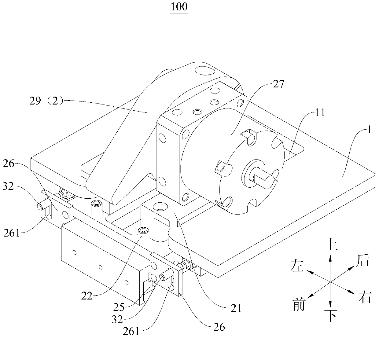
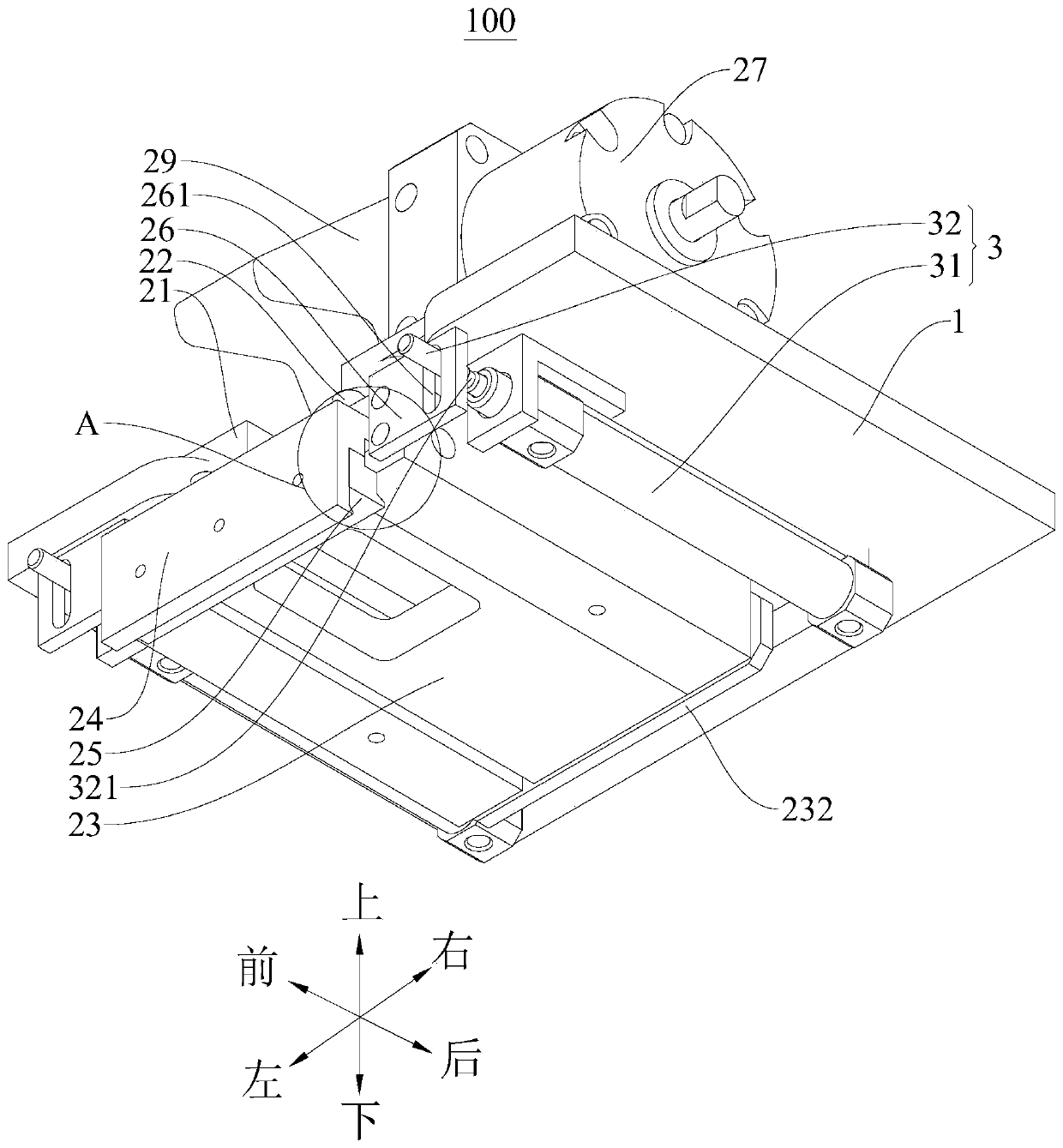
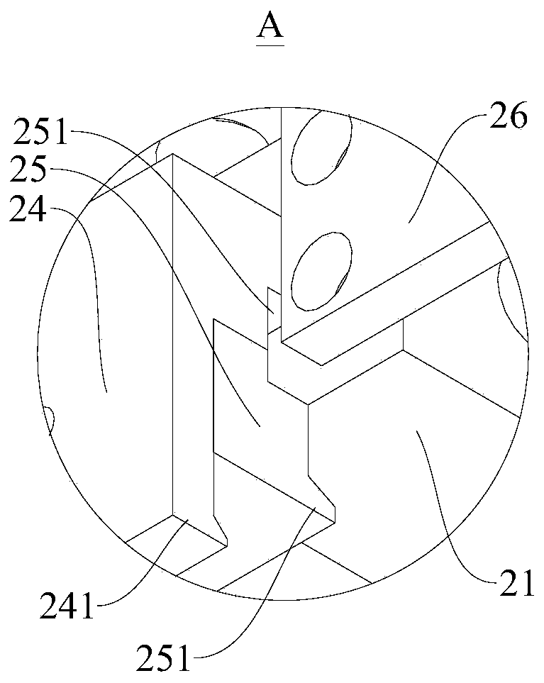
The invention discloses a floor knocking device. The floor knocking device comprises a fixed plate, an assembling plate, a hook plate and a knocking assembly, a first mounting groove extending in thefront and back direction is formed in the fixed plate, the assembling plate is movably mounted on the first mounting groove, a third mounting groove extending in the front and back direction is formedin the assembling plate, the hook plate is movably mounted in the third mounting groove, a second knocking groove is formed in the middle of the hook plate, a mounting hook is formed on the front endof the hook plate, and is suitable for hooking the side face of a floor, the knocking assembly is mounted on the assembling plate, and comprises a knocking hammer, and the knocking hammer is suitablefor knocking the rear side wall of the second knocking groove. According to the floor knocking device, the mounting gap between the floors can be reduced, the mounting hook can be well prevented frombeing damaged, in addition, the floor knocking device has the larger work range, reliability is high, and practicability is good.

Description

technical field [0001] The invention relates to the technical field of construction robots, in particular to a floor knocking device and a floor installation robot having the same. Background technique [0002] In the related art, the floor needs to be laid manually. During the installation of the floor, there is an installation gap between two adjacent floors. Workers usually use a percussion mallet to hit the floor to reduce the installation gap of the floor. , but it is easy to damage the floor, thus affecting the installation effect of the floor. Contents of the invention [0003] The present invention aims to solve at least one of the technical problems existing in the prior art. Therefore, an object of the present invention is to provide a floor knocking device, which can prevent floor damage and has a better installation effect. [0004] The invention also proposes a floor installation robot with the floor knocking device. [0005] According to the floor knocking...

Claims


Application Information

Patent Timeline
Patent Type & Authority Applications(China)
IPC IPC(8): E04F21/22
CPCE04F21/22
Inventor 秦博远周伟安
Owner GUANGDONG BOZHILIN ROBOT CO LTD
Why Eureka
Try Eureka