Stand column pouring template

A column and formwork technology, which is applied in the field of column pouring formwork, can solve problems such as waste of steel, and achieve the effects of saving steel, improving pouring efficiency, and saving construction sites

Pending Publication Date: 2020-07-10
上海崇创机电科技有限公司
0 Cites 2 Cited by

AI-Extracted Technical Summary

Problems solved by technology

[0004] The purpose of the present invention is to overcome the shortcoming of wasting...

Abstract

The invention discloses a stand column pouring template, and relates to the technical field of stand column construction. A plurality of side plates for pouring the side face of a stand column and a plurality of corner components for pouring the corners of the stand column are included. A columnar structure is defined by the side plates and the corner components at intervals. The side plates are detachably connected with the corner components adjacent to the side plates. The side plates are used for pouring the side face of the stand column, the corner components are used for pouring chamfersof the stand column, and the side plates are of a flat plate structure. Stand columns different in size can be poured by changing the effective length of the side plates, and accordingly steel waste can be avoided.

Application Domain

Forms/shuttering/falseworks

Technology Topic

Structural engineeringBoard structure +1

Image

  • Stand column pouring template
  • Stand column pouring template
  • Stand column pouring template

Examples

  • Experimental program(4)

Example Embodiment

[0022] Example 1:
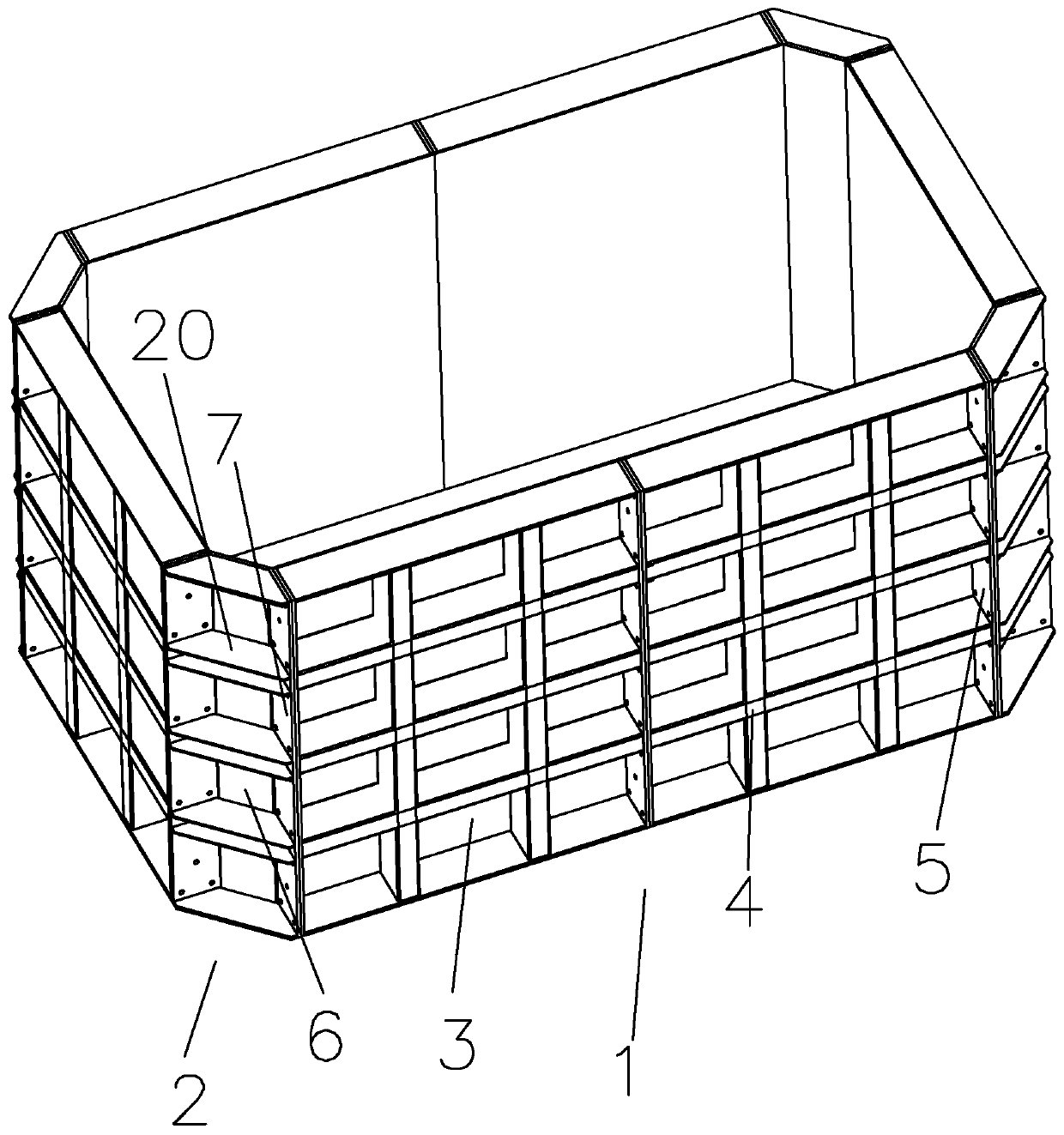
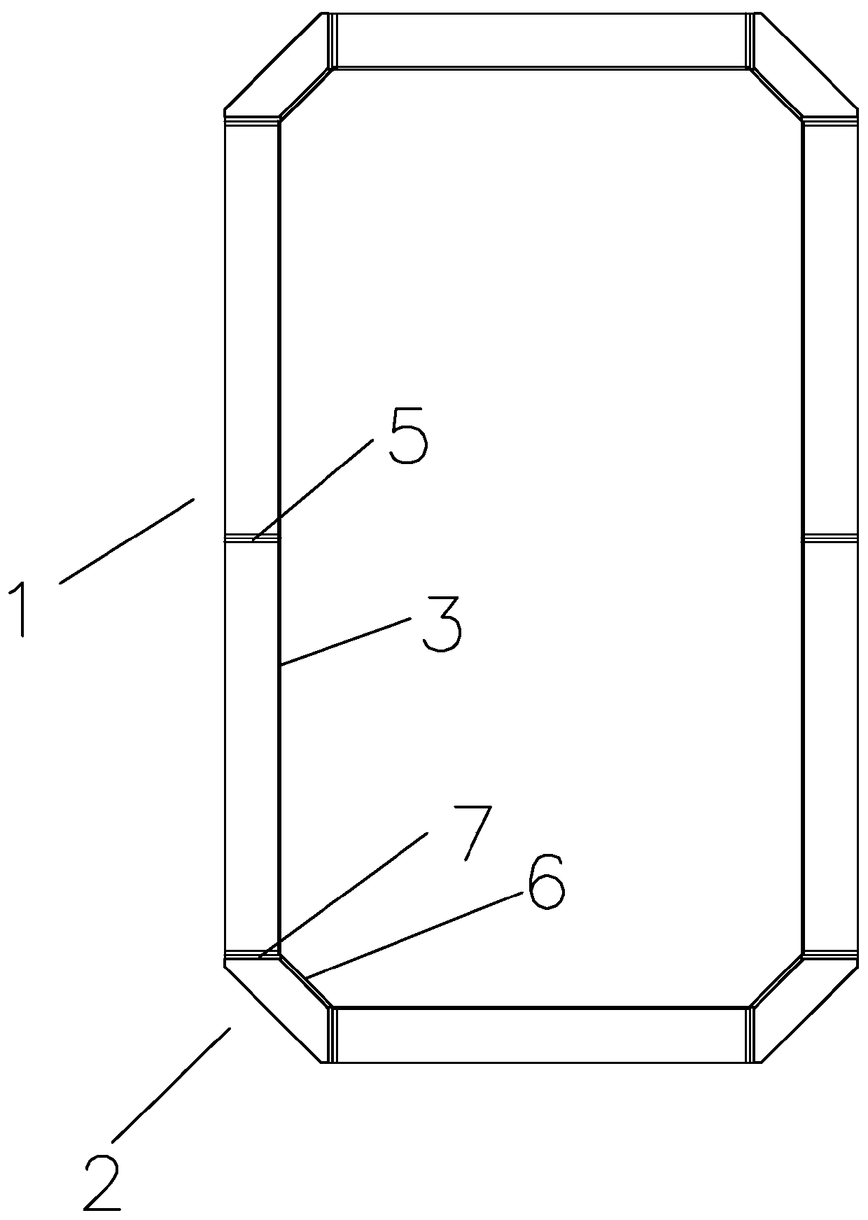
[0023] see Figure 1 to Figure 2 ,
[0024] A formwork for pouring a column, including several side plate parts 1 for pouring the side of the column, and several corner parts 2 for pouring the corners of the column. The side plate parts 1 and the corner parts 2 are arranged at intervals to form a column structure. The side panel 1 is detachably connected to its adjacent corner part 2; the corner part 2 is located at the edge of the corresponding side panel 1, and the side panel 1 includes at least one side panel module, and the side panel module includes pouring Side plate 3, a connecting plate 5 positioned at the edge of the pouring side plate 3, the corner part 2 includes a corner pouring side plate 6, a second connecting plate 7 positioned at the edge of the corner pouring side plate 6, the corner pouring side plate 6 is Planar or arc-shaped; the connecting plate 5 on the side of the side plate 1 adjacent to the corner part 2 and the corresponding second connecting plate 7 are connected by bolts; the pouring side plate 3 is provided with a Stiffeners 4 to increase the out-of-plane rigidity and the corner pouring side panels 6 are provided with reinforcing plates 20 for increasing the out-of-plane rigidity.

Example Embodiment

[0025] Embodiment principle:
[0026] It should be noted that the inner side mentioned in this article refers to the side facing the inside of the formwork.
[0027] When pouring, the side plate 1 is a flat plate structure, which is used to pour the side of the column, and the corner part 2 is used to pour the chamfer of the column. When it is necessary to pour columns of different sizes, just replace the side plate with a different width That is, since the side plate part is composed of at least one side plate formwork, assuming that the width of the side plate formwork is 500, when a side plate part with a width of 1000 is required, the two side plate formworks can be connected by bolts. By analogy, when the side panels are assembled, the side panel modules are spliced ​​together in turn, and the connecting panels are connected by bolts; for columns of different heights, in the same way, multiple side panels (corner parts) are stacked up and down to meet the requirements. Columns of different heights are poured, and after being stacked up and down, the upper and lower pouring side plates 3 are connected by bolts at the corresponding connecting plates. Similarly, the upper and lower corner parts are connected by bolts at the corresponding second connecting plates 7.

Example Embodiment

[0028] Example 2:
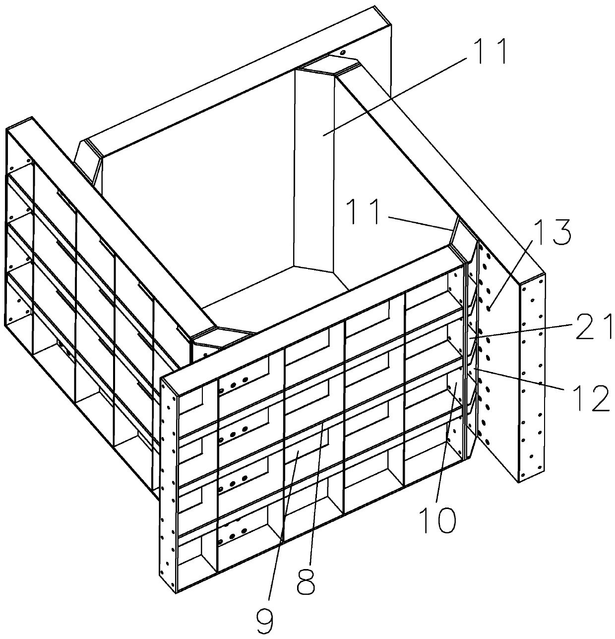
[0029] see Figure 3 to Figure 4 , a formwork for pouring a column, comprising several side plate parts 1 for pouring the sides of the column, several corner parts 2 for pouring the corners of the column, the side plate parts 1 and the corner parts 2 are arranged at intervals to form a column structure, The side panel 1 is detachably connected to its adjacent corner part 2; the side panel 1 includes a second casting side panel 9, a third connecting panel 10 located at the edge of the second casting side panel 9, and the corner part 2 includes a second corner casting side plate 11, a fourth connecting plate 12 located at the edge of the second corner casting side plate 11, the second corner casting side plate 11 is planar or arc-shaped, and the second One side of the corner pouring side plate 11 abuts against the edge of the second pouring side plate 9 on the corresponding side, and the other side of the second corner pouring side plate 11 abuts against the inner side of the second pouring side plate 9 on the corresponding side , the second pouring side plate 9 is provided with a number of adjusting bolt holes 13, the fourth connecting plate 12 on the side of the second corner pouring side plate 11 is attached to the corresponding third connecting plate 10 and connected by bolts, The fourth connecting plate 12 on the other side of the second corner pouring side plate 11 is connected to the adjusting bolt hole 13 by bolts, and the second pouring side plate 9 is provided with a plug for blocking the adjusting bolt hole 13; The second pouring side plate 9 is provided with a second stiffener 8 for increasing its out-of-plane rigidity, and the second corner pouring side plate 11 is provided with a second reinforcing plate 21 for increasing its out-of-plane rigidity.
[0030] Embodiment principle:
[0031] Although Embodiment 1 can save material, because the side plate parts are assembled by the side plate formwork, it is very troublesome to assemble the side plate parts when pouring columns of different sizes; in addition, due to the width of the side plate formwork, it is impossible to It is very small, resulting in a relatively large variation interval of the length and width values ​​of the column, and Embodiment 1 has the disadvantage of being inflexible.
[0032] When implementing Embodiment 2, to deal with columns of different sizes, as long as the corner parts are connected to different positions inside the second pouring side plate 9; Use plugs to block other adjusting bolt holes 13 to prevent concrete from flowing out of the pouring formwork. This embodiment greatly accelerates the assembly speed. flexible.

PUM

no PUM

Description & Claims & Application Information

We can also present the details of the Description, Claims and Application information to help users get a comprehensive understanding of the technical details of the patent, such as background art, summary of invention, brief description of drawings, description of embodiments, and other original content. On the other hand, users can also determine the specific scope of protection of the technology through the list of claims; as well as understand the changes in the life cycle of the technology with the presentation of the patent timeline. Login to view more.

Similar technology patents

Energy dissipating element of grouting sleeve

ActiveCN102505770Aperformance remains stablesave steel
Owner:上海同育建筑科技有限公司

Steel tube tower type fan combined structure

PendingCN114718815Asave materialsave steel
Owner:SOUTHWEST ELECTRIC POWER DESIGN INST OF CHINA POWER ENG CONSULTING GROUP CORP

Integrated protective window

InactiveCN102409951Asave steellow cost
Owner:陈帅

Classification and recommendation of technical efficacy words

  • save steel
  • Improve pouring efficiency

Electric control system of rubbish dumping transport car

InactiveCN102837923AImprove pouring efficiencyimprove working environment
Owner:上海派恩科技有限公司

Multi-station collaborative pouring system and pouring method

PendingCN114054740AShorten pouring timeImprove pouring efficiency
Owner:山东杰创机械有限公司

Simple feeding device and construction method thereof

PendingCN113530240AImprove pouring efficiencyLess waste of material loss
Owner:MCC5 GROUP CORP SHANGHAI

Aligning equipment for pouring technology

ActiveCN111922325AImprove pouring efficiencyEasy to clean and maintain
Owner:MAANSHAN XINGLONG FOUNDRY CO LTD

Horizontal line casting machine

InactiveCN112692266AReduced pouring timeImprove pouring efficiency
Owner:江阴远景铸造机械有限公司
Why Eureka
Try Eureka