
Buffering mechanism, vertical furnace and process door of vertical furnace

A buffer mechanism and vertical furnace technology, applied in vertical furnaces, furnaces, furnace components, etc., can solve the problems of poor sealing of the process door and uneven pressing force of the process door, and achieve uniform pressing force and sealing effect. The best effect of improving safety

Pending Publication Date: 2020-07-10
BEIJING NAURA MICROELECTRONICS EQUIP CO LTD
View PDF6 Cites 1 Cited by
  • Summary
  • Abstract
  • Description
  • Claims
  • Application Information

AI Technical Summary

Problems solved by technology

[0004] In view of the shortcomings of the existing methods, this application proposes a buffer mechanism, a vertical furnace and its process door to solve the technical problems of the prior art such as uneven compression force of the process door and poor sealing of the process door.

Method used


Image

  • Buffering mechanism, vertical furnace and process door of vertical furnace
  • Buffering mechanism, vertical furnace and process door of vertical furnace
  • Buffering mechanism, vertical furnace and process door of vertical furnace

Examples


Embodiment Construction

[0024] The present application is described in detail below, and examples of embodiments of the present application are shown in the drawings, wherein the same or similar reference numerals denote the same or similar components or components having the same or similar functions throughout. Also, detailed descriptions of known technologies will be omitted if they are not necessary to illustrate the features of the present application. The embodiments described below by referring to the figures are exemplary only for explaining the present application, and are not construed as limiting the present application.

[0025] Those skilled in the art can understand that, unless otherwise defined, all terms (including technical terms and scientific terms) used herein have the same meanings as commonly understood by those of ordinary skill in the art to which this application belongs. It should also be understood that terms, such as those defined in commonly used dictionaries, should be ...


PUM


Abstract

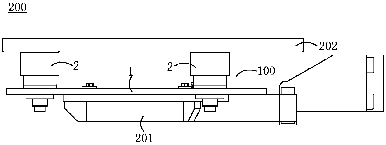
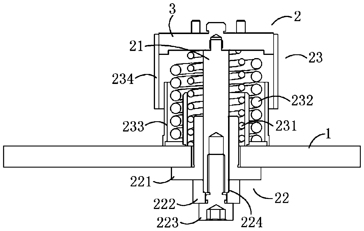
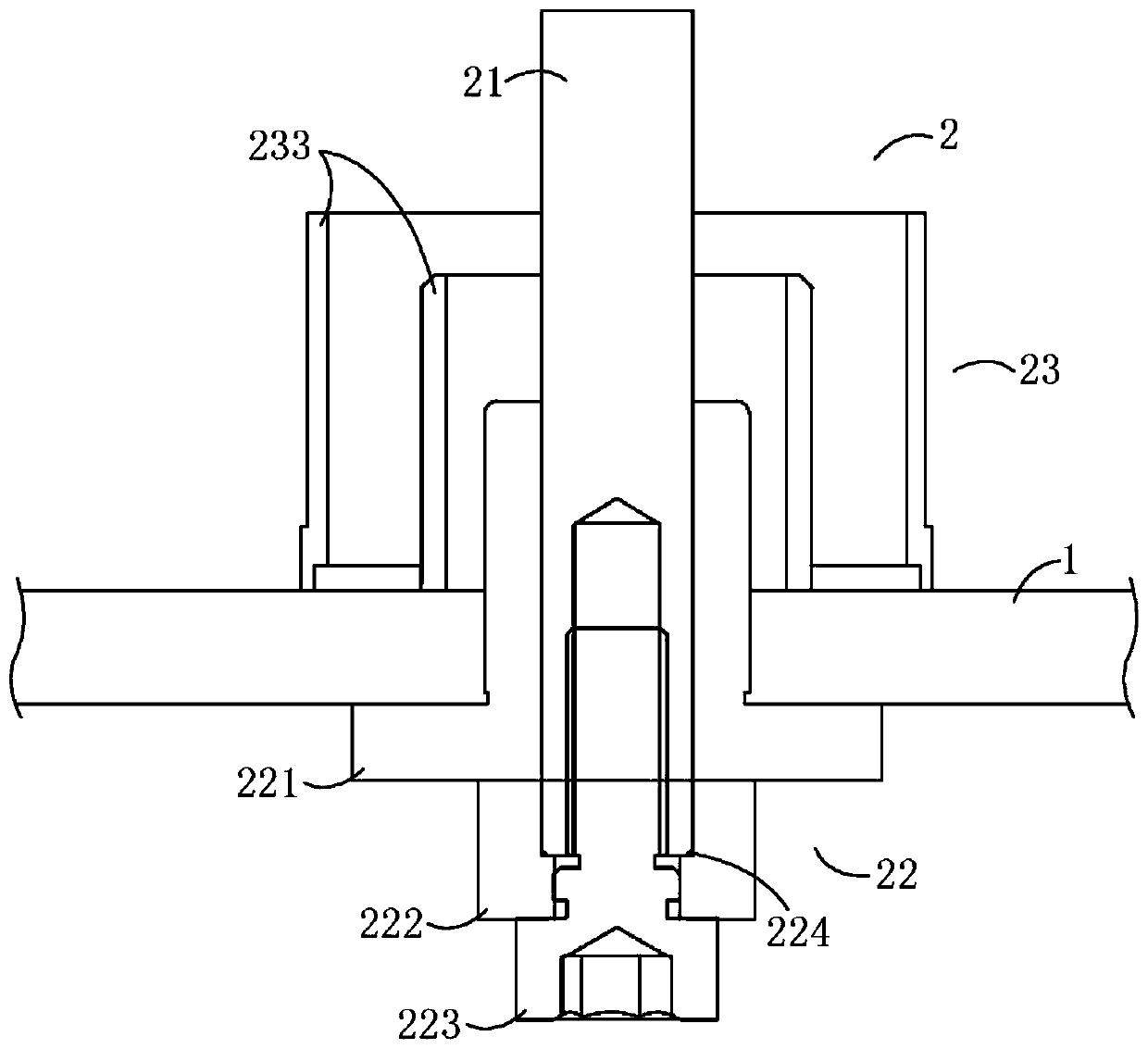
The embodiment of the invention provides a buffering mechanism, a vertical furnace and a process door of the vertical furnace. The buffering mechanism is arranged between a supporting arm and a sealing disc of the process door of the vertical furnace, and comprises a mounting plate and buffers. The mounting plate is arranged on the supporting arm. The multiple buffers are evenly distributed on themounting plate. The buffers comprise guide rods, guide assemblies and elastic assemblies. The top ends of the guide rods are connected with the sealing disc, the bottom ends of the guide rods are arranged on the mounting plate through the guide assemblies in a penetrating manner, and the guide rods can slide in the vertical direction relative to the mounting plate. The guide assemblies are arranged on the mounting plate and used for guiding the guide rods to slide in the vertical direction. The elastic assemblies sleeve the outer sides of the guide rods, are located between the mounting plateand the sealing disc, and are used for buffering pressing force applied to the sealing disc by the supporting arm. It can be guaranteed that the sealing disc does not deviate during force bearing, thus, the sealing effect of the sealing disc for a process cavity is good, and the safety of the process door and the process cavity is improved.

Description

technical field [0001] The application relates to the technical field of semiconductor processing, in particular, the application relates to a buffer mechanism, a vertical furnace and a process door thereof. Background technique [0002] At present, vertical heat treatment equipment is used as the front-end process equipment in the semiconductor manufacturing process, mainly for heat treatment processes such as oxide film, annealing and low-pressure chemical vapor deposition. During the heat treatment process, ethylene dichloride (C 2 h 2 Cl 2 ), Chlorine (Cl 2 ) or hydrogen chloride (HCl) and other process gases. The process chamber is the space for the heat treatment process, and it needs to be strictly sealed during the heat treatment process. On the one hand, it prevents the external environment from affecting the process chamber, and on the other hand, it prevents the process gas inside the process chamber from leaking. [0003] The process door is arranged at the ...

Claims


Application Information

Patent Timeline
IPC IPC(8): F27B1/10F27D1/18H01L21/67
CPCF27B1/10F27D1/1858H01L21/67098
Inventor 宋新丰
Owner BEIJING NAURA MICROELECTRONICS EQUIP CO LTD
Learn More