
Circuit, method and device for over-current turn-off test of converter valve

A converter valve, overcurrent technology, applied in the direction of measuring devices, circuit breaker testing, measuring electricity, etc., can solve problems such as unsatisfactory, IGBT heating, increase circuit complexity and investment costs, and achieve high equivalence. Submit The effect of trial efficiency

Pending Publication Date: 2020-07-10
XJ ELECTRIC +3
View PDF4 Cites 6 Cited by
  • Summary
  • Abstract
  • Description
  • Claims
  • Application Information

AI Technical Summary

Problems solved by technology

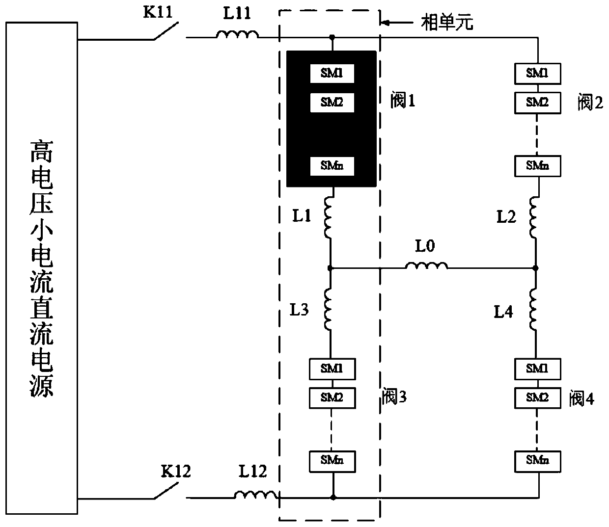
[0004] At present, there are mainly the following problems in the patents of the MMC valve IGBT overcurrent shutdown test at home and abroad: First, the IGBT overcurrent is generated by using the MMC valve to discharge the load. The requirements for the test under high temperature conditions; the second is to add an additional discharge circuit on the basis of the MMC valve operation test to conduct the IGBT overcurrent test. This method solves the problem of IGBT heating, but requires additional equipment on the basis of the original circuit to improve Reduced circuit complexity and investment cost

Method used


Image

  • Circuit, method and device for over-current turn-off test of converter valve
  • Circuit, method and device for over-current turn-off test of converter valve
  • Circuit, method and device for over-current turn-off test of converter valve

Examples


Embodiment Construction

[0044] In order to make the object, technical solution and advantages of the present invention clearer, the present invention will be further described in detail below in combination with specific embodiments and with reference to the accompanying drawings. It should be understood that these descriptions are exemplary only, and are not intended to limit the scope of the present invention. Also, in the following description, descriptions of well-known structures and techniques are omitted to avoid unnecessarily obscuring the concept of the present invention.

[0045] In order to make the purpose, technical solutions and advantages of the embodiments of the present invention clearer, the technical solutions in the embodiments of the present invention will be clearly and completely described below in conjunction with the accompanying drawings. Obviously, the described embodiments are part of the embodiments of the present invention, and Not all examples. Based on the embodiments...


PUM


Abstract

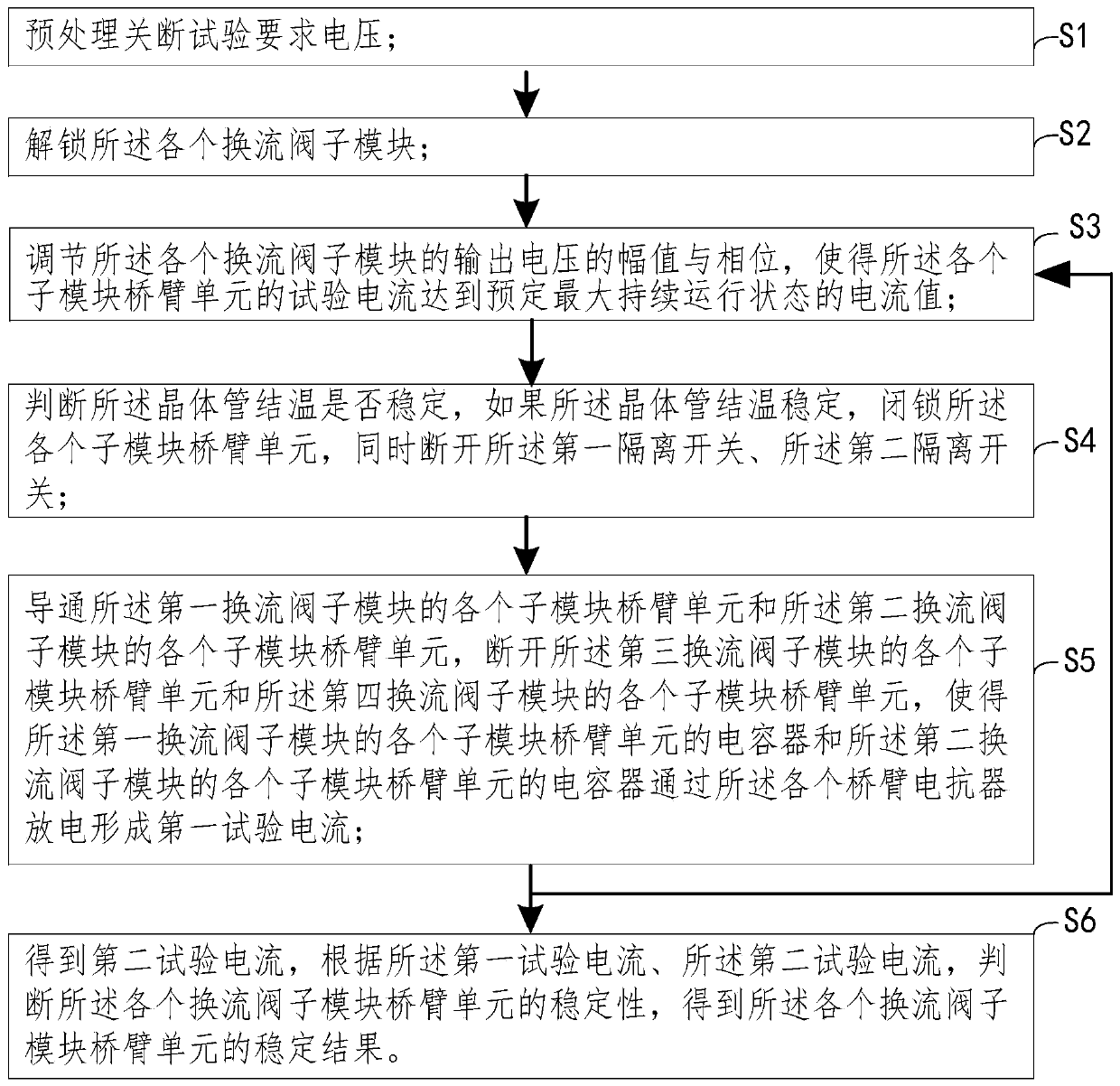
The invention discloses a circuit, a method and a device for an over-current turn-off test of a converter valve. The test circuit comprises a direct-current power supply, an isolating switch, a filterreactor and at least two phase units. Each phase unit comprises at least two converter valves, a bridge arm reactor and a load reactor, and the converter valves are connected through the bridge arm reactor; alternating current sides of the at least two phase units are connected through the load reactor; direct current sides of the at least two phase units are connected; and the direct-current power supply is connected with each direct-current side of each phase unit through the isolating switch and the filter reactor. A converter valve maximum continuous operation test and a transistor overcurrent turn-off test can be performed in one circuit at the same time, an equipment utilization rate is improved, and investment cost is reduced; and meanwhile, the test circuit is stable and reliablein operation, and meets technical requirements of the converter valve over-current turn-off test.

Description

technical field [0001] The invention relates to the field of flexible direct current transmission converter valve testing, in particular to a circuit, method and device for overcurrent shutoff testing of a converter valve. Background technique [0002] The flexible HVDC transmission technology (Voltage Source Converter Based HVDC, VSC-HVDC) based on Modular Multilevel Converter (Modular Multilevel Converter, MMC) is more and more widely used in power systems, and its voltage level is becoming more and more High, the current level is getting bigger and bigger. In order to ensure the reliability of its key equipment - MMC valve, engineering puts forward higher requirements for its electrical performance, especially for the ability to withstand various extreme currents, voltages and thermal stresses under fault conditions. Require. Therefore, before the project is put into operation, a series of tests must be carried out on the MMC valve in accordance with the standards to ve...

Claims


Application Information

Patent Timeline
Patent Type & Authority Applications(China)
IPC IPC(8): G01R31/26G01R31/27G01R31/327
CPCG01R31/2617G01R31/2619G01R31/27G01R31/3274
Inventor 常忠廷张坤胡四全范彩云陈二松李娟甄帅才利存王梁
Owner XJ ELECTRIC
Learn More