Optical lens, manufacturing method of optical lens and optical imaging device

A technology for optical lenses and manufacturing methods, applied in the field of optical lenses and optical imaging devices, capable of solving problems such as poor anti-reflection effects of optical lenses

Pending Publication Date: 2020-07-10
ZHEJIANG SUNNY OPTICAL CO LTD
View PDF0 Cites 2 Cited by
  • Summary
  • Abstract
  • Description
  • Claims
  • Application Information

AI Technical Summary

Problems solved by technology

[0007] The main purpose of the present invention is to provide an optical lens, a manufacturing method of the optical len...

Method used


Image

  • Optical lens, manufacturing method of optical lens and optical imaging device
  • Optical lens, manufacturing method of optical lens and optical imaging device
  • Optical lens, manufacturing method of optical lens and optical imaging device

Examples


Embodiment 1

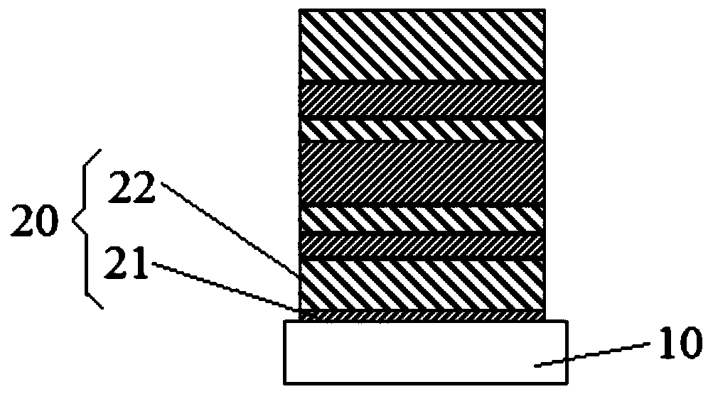
[0056] exist image 3 In the specific embodiment shown, the optical lens includes a lens base 10 and an anti-reflection film system 20, and the structure of the optical lens is: Sub / (HL)^m / Air, where m=4, that is, starting from the lens base 10, The first layer is a high-refractive-index film layer 21, the second layer is a low-refractive-index film layer 22, the third layer is a high-refractive-index film layer 21, and the fourth layer is a low-refractive index film layer 22, repeating this four times. In this embodiment, the high refractive index film layer 21 is made of Ti 3 o 5 composition, and the high refractive index film layer 21 is 2.26, and the material of the low refractive index film layer 22 is Al 2 o 3 and SiO 2 mixture, and the low refractive index film layer 22 has a refractive index of 1.46. In this embodiment, the thickness of each film layer from the direction close to the lens substrate 10 to away from the lens substrate 10 is: 10.28nm, 57.22nm, 12.75n...

Embodiment 2

[0064] The difference from the first embodiment is that the specific structure of the anti-reflection film system 20 is different.

[0065]In this embodiment, the optical lens includes a lens base 10 and an anti-reflection film system 20, and the structure of the optical lens is: Sub / L(HL)^m / Air, where m=4, that is, starting from the lens base 10, the first One layer is a low refractive index film layer 22, the second layer is a high refractive index film layer 21, the third layer is a low refractive index film layer 22, the fourth layer is a high refractive index film layer 21, and the fifth layer is a low refractive index film layer. Film layer 22, the sixth layer is a high refractive index film layer 21, the seventh layer is a low refractive index film layer 22, the eighth layer is a high refractive index film layer 21, and the ninth layer is a low refractive index film layer 22, to ensure The low refractive index film layer 22 is in contact with air. In this embodiment, t...

Embodiment 3

[0068] The difference from the first embodiment is that the material of the anti-reflection film system 20 is different.

[0069] In this embodiment, the optical lens includes a lens base 10 and an anti-reflection film system 20, and the structure of the optical lens is: Sub / (HL)^m / Air, where m=4, that is, starting from the lens base 10, the first The first layer is a high refractive index film layer 21, the second layer is a low refractive index film layer 22, the third layer is a high refractive index film layer 21, and the fourth layer is a low refractive index film layer 22, so repeat four times. In this embodiment, the high refractive index film layer 21 is made of Ta 2 o 5 composition, and the high refractive index film layer 21 is 2.22, and the material of the low refractive index film layer 22 is SiO 2 , and the low refractive index film layer 22 has a refractive index of 1.48. In this embodiment, the thicknesses of the film layers from the direction close to the le...


PUM


Abstract

The invention provides an optical lens, a manufacturing method of the optical lens and an optical imaging device. The optical lens includes: a lens substrate; an anti-reflection film system which is arranged on at least one surface of the lens substrate, wherein the anti-reflection film system comprises a plurality of high-refractive-index film layers and a plurality of low-refractive-index film layers, the high-refractive-index film layers and the low-refractive-index film layers are alternately stacked and the low-refractive-index film layers are in contact with air, and the reflectivity ofthe optical lens to light with the wavelength larger than or equal to 600 nanometers and smaller than or equal to 730 nanometers is smaller than 2%. The problem that the optical lens in the prior artis poor in antireflection effect is solved.

Description

technical field [0001] The invention relates to the technical field of optical imaging equipment, in particular to an optical lens, a manufacturing method of the optical lens and an optical imaging device. Background technique [0002] The brightness of an object or surface illuminated by a light source is called illuminance, and relative illuminance is the ratio of peripheral illuminance to central illuminance. If the relative illumination is too low, the center of the image is brighter, while the surrounding area is darker, that is, vignetting phenomenon, commonly known as vignetting. If the relative illumination is too low, it will also lead to color distortion, and in severe cases, there will be a "missing corner" phenomenon where the four corners are all black. This is because the luminous flux of the lens gradually decreases from the center to the edge, that is, the luminous flux at the center of the lens is greater than that at the edge, resulting in poor consistency...

Claims


Application Information

Patent Timeline
IPC IPC(8): G02B1/115C23C14/24C23C14/08C23C14/10
CPCC23C14/081C23C14/083C23C14/10C23C14/24G02B1/115
Inventor 蒯泽文阮高梁袁银潮
Owner ZHEJIANG SUNNY OPTICAL CO LTD
Why Eureka
Try Eureka