Supercharge Your Innovation With Domain-Expert AI Agents!

ECU flashing device and flashing method

A writing device and writing control technology, applied in the direction of instruments, electrical testing/monitoring, control/regulation systems, etc., can solve the problems of high price and complex structure of ECU flashing tools

Inactive Publication Date: 2020-07-10
北京汽车动力总成有限公司
View PDF5 Cites 2 Cited by
  • Summary
  • Abstract
  • Description
  • Claims
  • Application Information

AI Technical Summary

Problems solved by technology

[0005] The embodiment of the present invention provides an ECU flashing device and a flashing method, which are used to solve the problem that the structure of the ECU flashing tool is complicated and the price is relatively expensive in the prior art

Method used


Image

  • ECU flashing device and flashing method
  • ECU flashing device and flashing method
  • ECU flashing device and flashing method

Examples


Embodiment Construction

[0032] The following will clearly and completely describe the technical solutions in the embodiments of the present invention with reference to the accompanying drawings in the embodiments of the present invention. Obviously, the described embodiments are some of the embodiments of the present invention, but not all of them. Based on the embodiments of the present invention, all other embodiments obtained by persons of ordinary skill in the art without creative efforts fall within the protection scope of the present invention.

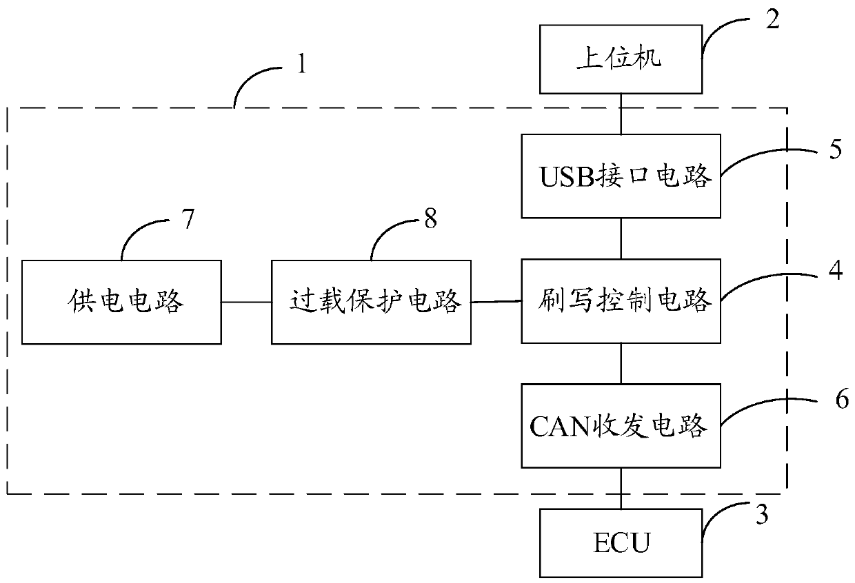
[0033] Please refer to figure 1 as shown, figure 1 It is a schematic structural diagram of an ECU flashing device 1 provided by an embodiment of the present invention. The embodiment of the present invention provides an ECU flashing device 1 for flashing an ECU3. The ECU flashing device 1 includes a universal serial bus USB interface circuit 5, controller area network CAN transceiver circuit 6 and flashing control circuit 4;

[0034] USB interface ci...


PUM


Abstract

The embodiment of the invention provides an ECU flashing device and flashing method. The ECU flashing device comprises a universal serial bus (USB) interface circuit, a controller area network (CAN) transceiving circuit and a flashing control circuit. Tthe USB interface circuit is used for carrying out USB communication with an upper computer; the CAN transceiving circuit is used for carrying outCAN communication with an electronic control unit (ECU). A first terminal of the flashing control circuit is connected with the USB interface circuit; a second terminal of the flashing control circuitis connected with the CAN transceiving circuit, and the flashing control circuit is used for acquiring flashing data sent by the upper computer through the USB interface circuit and sending the flashing data to the ECU through the CAN transceiving circuit for flashing. The ECU flashing device provided by the embodiment of the invention is simple in structure and relatively high in practicability.

Description

technical field [0001] Embodiments of the present invention relate to the technical field of automobiles, in particular to an ECU flashing device and flashing method. Background technique [0002] With the rapid development of automobile technology and electronic technology, the modern automobile industry has widely adopted electronic control technology in order to improve automobile power, economy, driving performance, safety, comfort, and reduce exhaust pollution. Electronic control technology is an important trend and symbol of the development of modern automobile technology, from engine fuel injection, ignition control, intake control, emission control, fault self-diagnosis to chassis transmission system, steering and braking system, as well as automatic transmission, body , Auxiliary devices, etc. have generally adopted electronic control technology, and the application of automotive electronic control technology has played an increasingly important role in the modern a...

Claims


Application Information

Patent Timeline
IPC IPC(8): G05B23/02
CPCG05B23/0213
Inventor 谢昊原于洪涛宋铁兵代培培谢立哲白宝国宫雨
Owner 北京汽车动力总成有限公司
Features
  • R&D
  • Intellectual Property
  • Life Sciences
  • Materials
  • Tech Scout
  • Unparalleled Data Quality
  • Higher Quality Content
  • 60% Fewer Hallucinations
Learn More