Array antenna vibration deformation prediction method and device based on main modal method and strain

An array antenna and prediction method technology, applied in the antenna field, can solve problems such as difficult to reflect antenna deformation, and achieve the effect of improving reconstruction accuracy

Active Publication Date: 2020-07-10
CHINA ELECTRONIC TECH GRP CORP NO 38 RES INST
View PDF2 Cites 6 Cited by
  • Summary
  • Abstract
  • Description
  • Claims
  • Application Information

AI Technical Summary

Problems solved by technology

[0005] The technical problem to be solved by the present invention is to provide an array antenna vibration deformation prediction method and equipment based on the principal mode method and strain, to solve the problem that it is difficult to reflect the actual deformation of the antenna in the study of the influence of random vibration on the deformation of the antenna structure

Method used


Image

  • Array antenna vibration deformation prediction method and device based on main modal method and strain
  • Array antenna vibration deformation prediction method and device based on main modal method and strain
  • Array antenna vibration deformation prediction method and device based on main modal method and strain

Examples


Embodiment 1

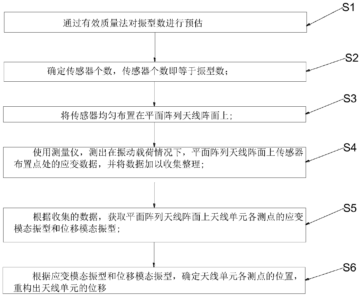
[0137] Such as figure 1 , an array antenna vibration deformation prediction method based on principal mode method and strain, including the following steps:

[0138] S1. The number of mode shapes is estimated by the effective mass method, including:

[0139] S11. Obtain the differential equation of the multi-degree-of-freedom system under the action of ground motion, as follows:

[0140]

[0141] Among them, M represents mass, C represents damping, K represents stiffness, I represents moment of inertia, represents the acceleration, represents velocity, x represents displacement, Actual ground motion acceleration.

[0142] Formula (1) is actually a coupled equation system, the displacement x of formula (1) is taken as displacement vector x, and then according to x j ={φ} i q i Perform principal coordinate transformation, where {φ} j is the displacement coordinate transformation matrix of the jth mode, q j is the displacement of the jth order modal particle relati...

Embodiment 2

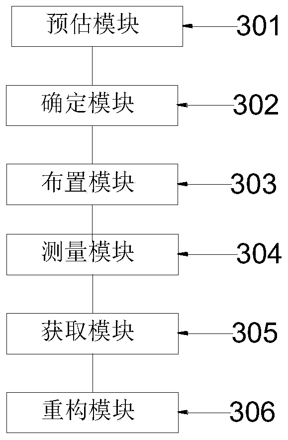
[0244] Prediction equipment for array antenna vibration deformation prediction method based on principal mode method and strain, including;

[0245] An estimation module for estimating the number of mode shapes by the effective mass method; also includes;

[0246] Obtain the differential equation of the multi-degree-of-freedom system under the action of ground motion, as follows:

[0247]

[0248] Among them, M represents mass, C represents damping, K represents stiffness, I represents moment of inertia, represents the acceleration, represents velocity, x represents displacement, Actual ground motion acceleration.

[0249] Formula (1) is actually a coupled equation system, the displacement x of formula (1) is taken as displacement vector x, and then according to x j ={φ} i q i Perform principal coordinate transformation, where {φ} j is the displacement coordinate transformation matrix of the jth mode, q j is the displacement of the jth order modal particle relati...


PUM


Abstract

The invention discloses an array antenna vibration deformation prediction method based on a main modal method and strain. The method comprises the steps: S1, estimating the vibration mode number through an effective mass method; S2, determining the number of sensors, wherein the number of sensors is equal to the number of vibration modes; S3, uniformly arranging sensors on the array surface of theplanar array antenna; S4, measuring the strain of a sensor arrangement point on the array plane of the planar array antenna under the condition of vibration load; S5, acquiring a strain modal shape and a displacement modal shape of each measuring point of the antenna unit on the planar array antenna array surface; S6, reconstructing the displacement of the antenna unit. The invention further discloses array antenna vibration deformation prediction equipment based on the main modal method and strain. According to the method, the strain measurement theory is utilized, the model characteristicsof the whole planar array antenna array surface are reflected by collecting the vibration deformation information of a few points of the antenna units, the displacement of the antenna units is reconstructed, and the reconstruction precision is improved.

Description

technical field [0001] The present invention relates to the technical field of antennas, in particular to methods and equipment for predicting vibration deformation of array antennas based on principal mode method and strain. Background technique [0002] With the development of electronic science and technology, antennas have gradually become indispensable electronic products, especially array antennas, which have become the main topic of antenna research in recent years. However, due to the particularity of its working environment, the array antenna is often affected by external vibration loads, so its electrical performance will be damaged, making it difficult to achieve expected working requirements. Therefore, it is very important to study the influence of vibration on the array antenna. [0003] As mentioned above, Harmen studied the influence of vibration on the electrical performance of conformal antennas, but in his research, he did not conduct random vibration ana...

Claims


Application Information

Patent Timeline
Patent Type & Authority Applications(China)
IPC IPC(8): G06F30/20
CPCY02T90/00
Inventor 王志海王璐张根烜于坤鹏毛亮王晓红时海涛鲍睿
Owner CHINA ELECTRONIC TECH GRP CORP NO 38 RES INST
Why Eureka
Try Eureka