
Piezoelectric MEMS microphone

A microphone, piezoelectric technology

Active Publication Date: 2020-07-10
AAC ACOUSTIC TECH (SHENZHEN) CO LTD
View PDF19 Cites 0 Cited by
  • Summary
  • Abstract
  • Description
  • Claims
  • Application Information

AI Technical Summary

Problems solved by technology

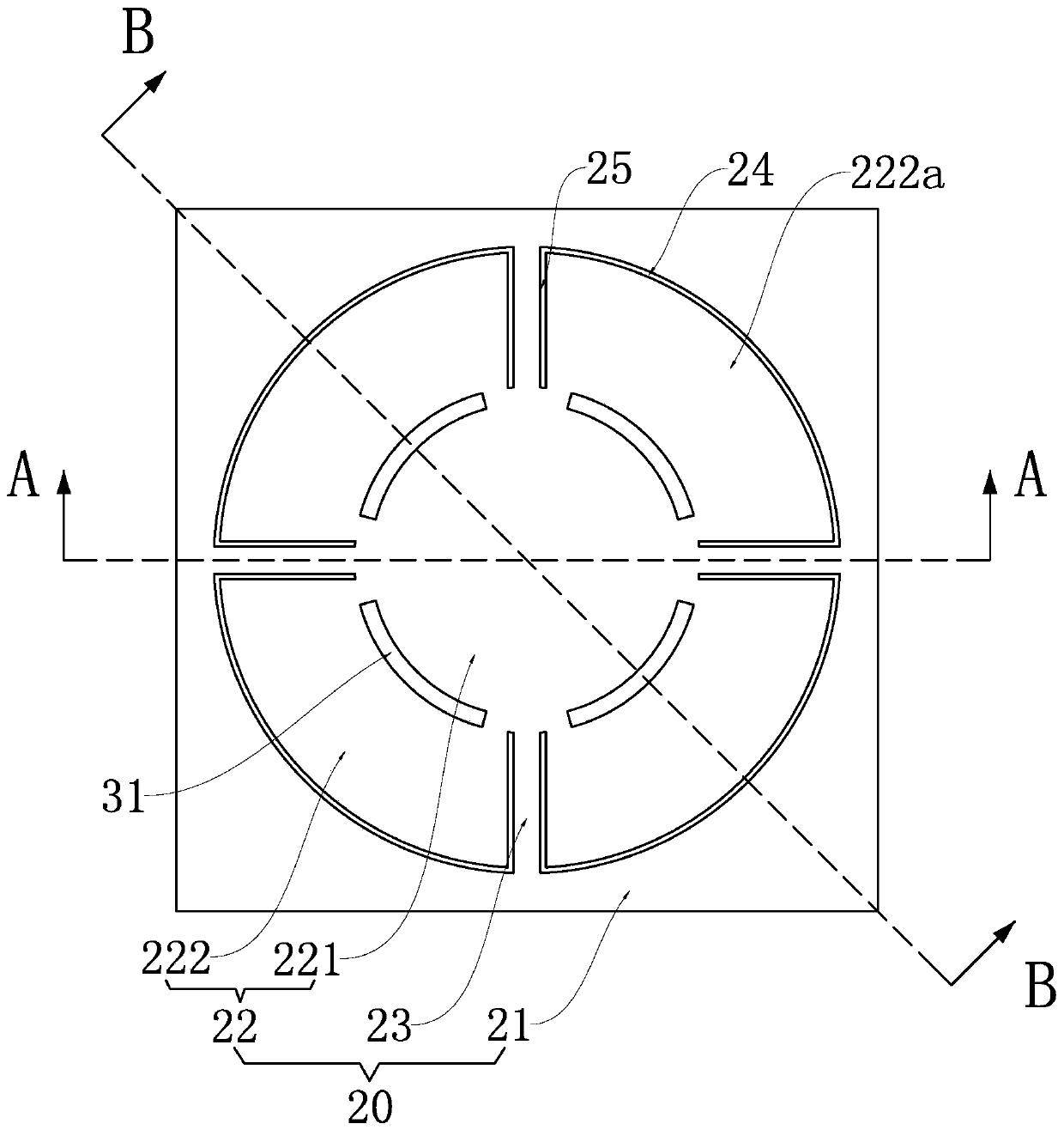
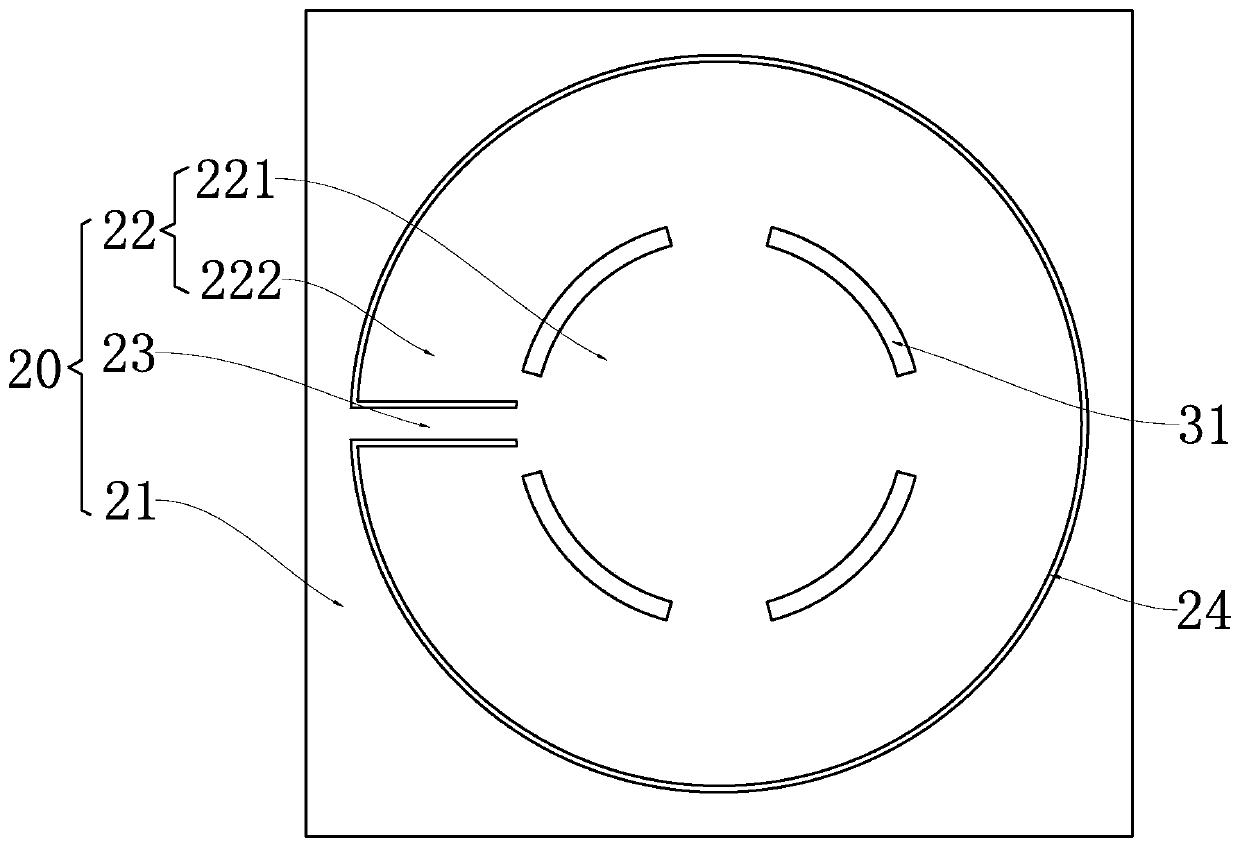
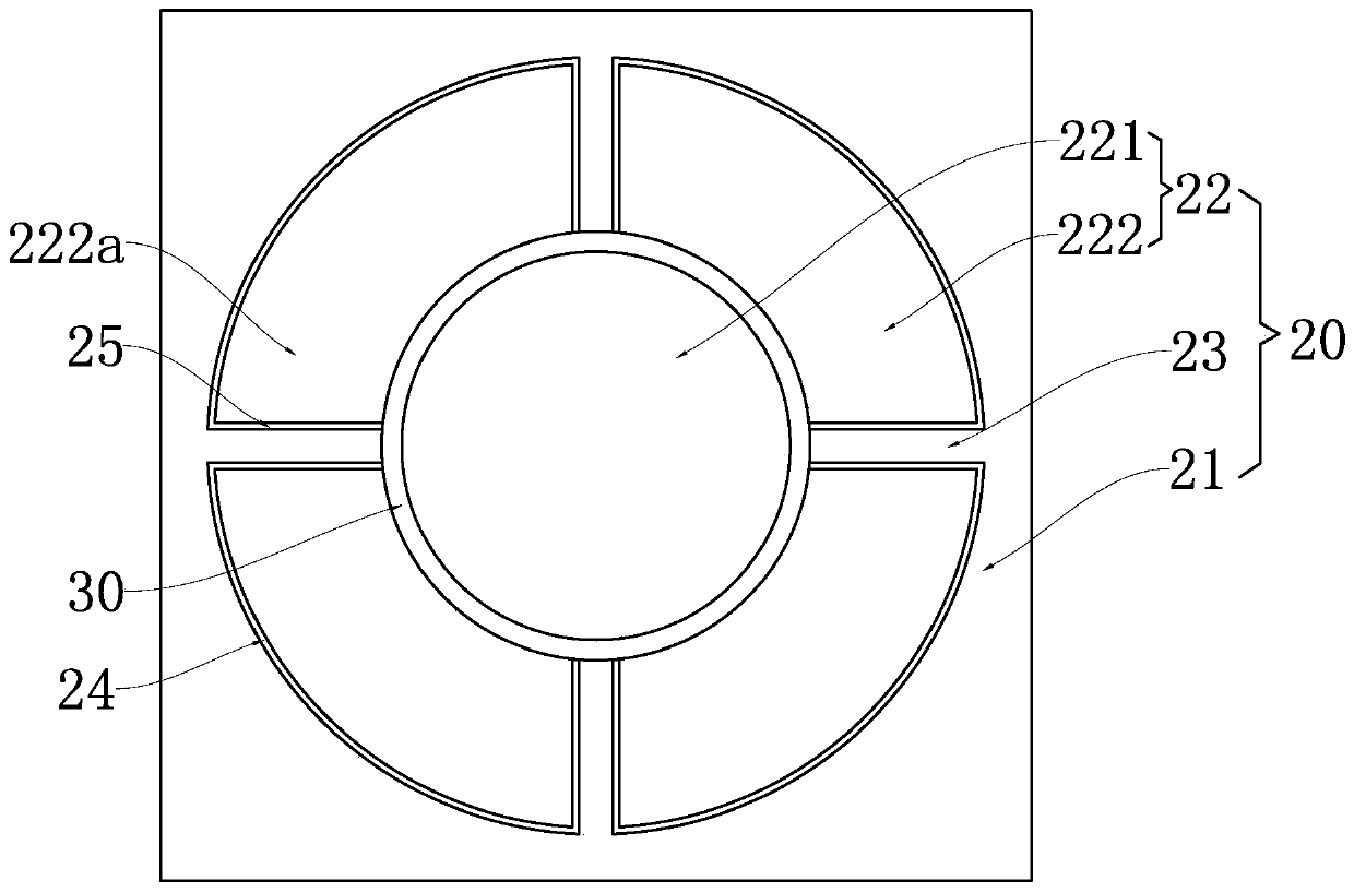
[0004] The purpose of the present invention is to provide a piezoelectric MEMS microphone to solve the problem of uneven deformation of the diaphragm in the prior art due to uneven stress distribution in the processing process, which in turn affects the sensitivity, resonance peak and low frequency attenuation of the microphone. technical issues of consistency

Method used


Image

  • Piezoelectric MEMS microphone
  • Piezoelectric MEMS microphone
  • Piezoelectric MEMS microphone

Examples


Embodiment Construction

[0024] It should be noted that, in the case of no conflict, the embodiments in the present application and the features in the embodiments can be combined with each other. The present invention will be described in detail below with reference to the accompanying drawings and examples.

[0025] It should be pointed out that the following detailed description is exemplary and intended to provide further explanation to the present application. Unless defined otherwise, all technical and scientific terms used herein have the same meaning as commonly understood by one of ordinary skill in the art to which this application belongs.

[0026] It should be noted that the terminology used here is only for describing specific implementations, and is not intended to limit the exemplary implementations according to the present application. As used herein, unless the context clearly dictates otherwise, the singular is intended to include the plural, and it should also be understood that wh...


PUM


Abstract

The invention relates to the technical field of acoustoelectric conversion and provides a piezoelectric MEMS microphone. The piezoelectric MEMS microphone comprises a substrate with a back cavity anda piezoelectric vibrating diaphragm, the piezoelectric vibrating diaphragm comprises a suspension part and a substrate fixing part connected with the substrate; the piezoelectric vibrating diaphragm further comprises a supporting part connected with the substrate fixing part and the suspension part, the suspension part is suspended above the back cavity through the supporting part; the piezoelectric MEMS microphone further comprises a limiting structure, the suspension part comprises a middle film overlapped with the projection range of the limiting structure in the vibration direction, and the limiting structure and the middle film form a fixing structure of the piezoelectric vibrating diaphragm. After the oxide layer of the piezoelectric vibrating diaphragm is released, the middle diaphragm deforms upwards or downwards under the action of residual stress in the piezoelectric vibrating diaphragm and is connected with the corresponding limiting structure so as to completely release stress and gradient stress. By applying the technical scheme, the technical problem that in the prior art, due to uneven stress distribution in the machining process, deformation of the diaphragm is notuniform, and then consistency of performance such as sensitivity of the microphone is affected is solved.

Description

【Technical field】 [0001] The invention relates to the technical field of acoustic-electric conversion, in particular to a piezoelectric MEMS microphone. 【Background technique】 [0002] Piezoelectric MEMS microphones have many advantages over traditional capacitive MEMS microphones, including dust and water resistance and higher maximum output sound pressure (AOP). Limited by the sputtering growth process of the piezoelectric film layer, the stress of the piezoelectric film layer is large and unevenly distributed, and there is a large gradient stress along the thickness direction of the film layer growth. The existence of these stresses and gradient stresses makes it impossible to avoid warping and deformation of the diaphragm, whether it is fixed around the diaphragm or locally fixed in the diaphragm. The warping and deformation of the diaphragm will further increase the gap of the vent slot, and the degree of deformation and warping is different, which is difficult to cont...

Claims


Application Information

Patent Timeline
IPC IPC(8): H04R19/00H04R19/04H04R7/18
CPCH04R7/18H04R19/005H04R19/04H04R2307/00
Inventor 段炼张睿
Owner AAC ACOUSTIC TECH (SHENZHEN) CO LTD
Learn More