Piezoelectric acoustic MEMS transducer and fabrication method thereof

a technology of acoustic mems and a fabrication method, applied in the direction of electrostatic transducers, miconductor electrostatic transducers, loudspeakers, etc., can solve the problems of reducing affecting the performance of the microphone, and affecting the reliability of the capacitive microphon

Active Publication Date: 2019-10-24
STMICROELECTRONICS SRL
View PDF0 Cites 7 Cited by
  • Summary
  • Abstract
  • Description
  • Claims
  • Application Information

AI Technical Summary

Benefits of technology

[0015]According to the present disclosure, a MEMS transducer and a fabrication method thereof are provided.

Problems solved by technology

However, microphones of this type are disadvantageous.
In fact, capacitive microphones may present reliability problems due to contamination by external particles and / or other contaminants (for example, water, dust, soldering vapors, etc.).
In particular, the external particles may be trapped between the electrodes of the capacitor, acting as mechanical blocks for the membrane deflection and generating electrical leakage paths, thus causing malfunctioning and a reduction in performance of the microphone.
In addition, the presence of contaminants between the electrodes of the capacitor may cause permanent damage to the microphone.
Consequently, it is not possible to use a capacitive MEMS microphone in an environment such as water.
However, the above known solution has some disadvantages.
This is undesirable, since the position of the roll-off-frequency point can vary up to ±50 Hz, being incompatible with current market requirements where, in many cases, it is desired to have a maximum variation of roll-off frequency of ±10 Hz.
Furthermore, the MEMS microphones of a piezoelectric type currently on the market have a low sensitivity and, thus, a low SNR (Signal-to-Noise Ratio, in particular due to the noise intrinsic in the MEMS microphone and caused by the material and by the viscous resistances generated by the movement of the air of the microphone).

Method used


Image

  • Piezoelectric acoustic MEMS transducer and fabrication method thereof
  • Piezoelectric acoustic MEMS transducer and fabrication method thereof
  • Piezoelectric acoustic MEMS transducer and fabrication method thereof

Examples


Embodiment Construction

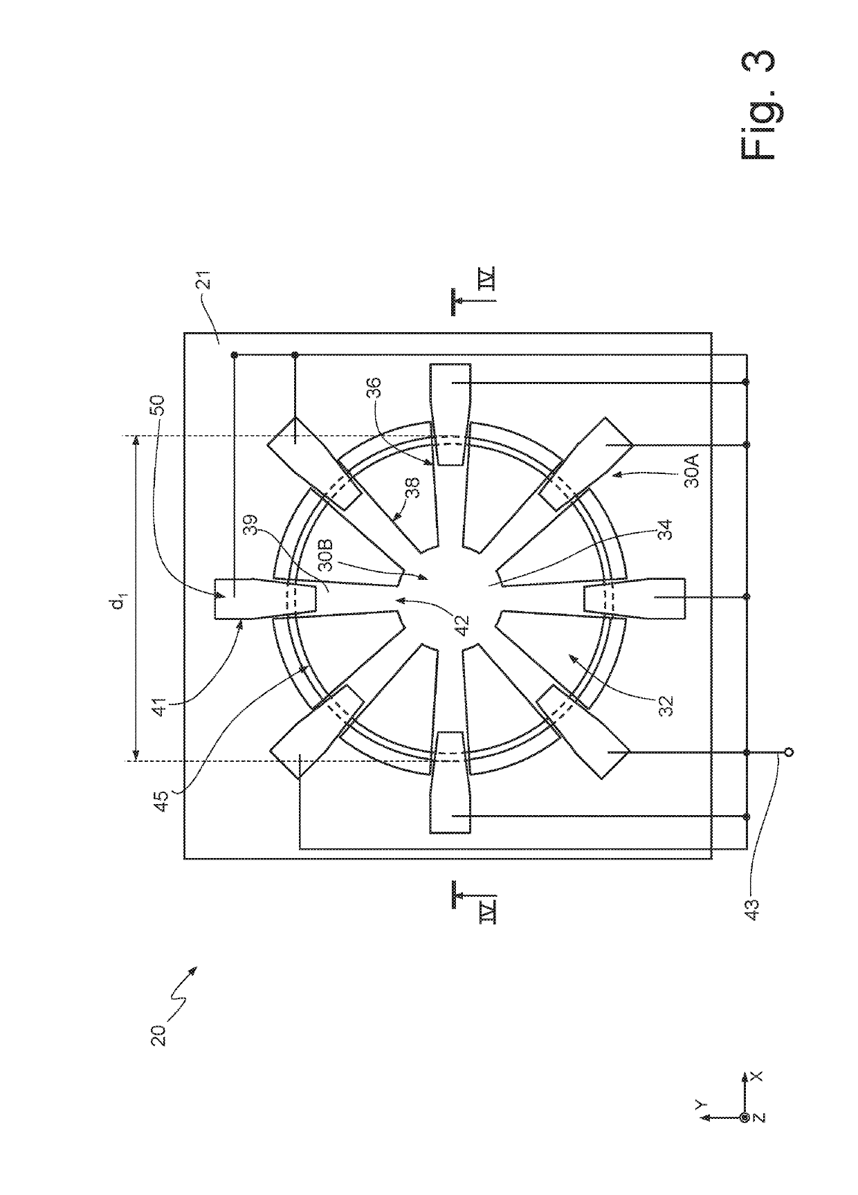
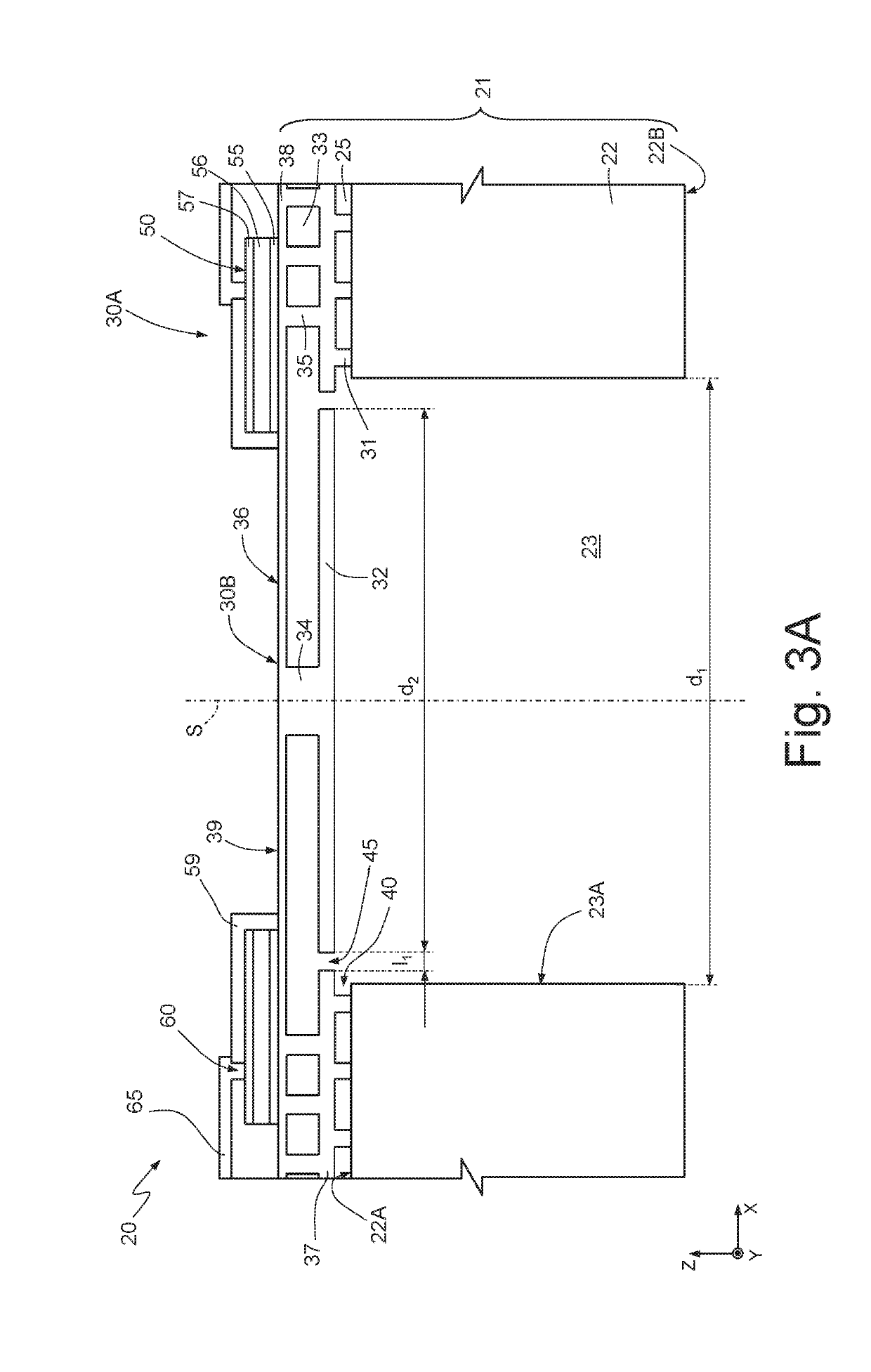
[0033]FIGS. 3 and 3A show an embodiment of an acoustic MEMS transducer, here forming a MEMS microphone 20. In particular, the MEMS microphone 20 is of a piezoelectric type. In addition, the present MEMS transducer may form an acoustic emitting element (for example, a speaker).

[0034]With reference to FIG. 3A, the MEMS microphone 20 is formed in a body 21 comprising a substrate 22 and a sensitive region 36. The substrate 22 is of semiconductor material (for example, silicon), having a first surface 22A and a second surface 22B. In particular, the substrate 22 has, in top plan view (FIG. 3) a quadrangular, for example rectangular, shape having a central axis S.

[0035]The substrate 22 is traversed, from the second surface 22B, by a through cavity 23 having, for example, in top plan view, a circular shape with diameter d1, laterally delimited by a wall 23A.

[0036]A first dielectric layer 25 extends on the first surface 22A and is, for example, of USG (Undoped Silicate Glass), thermal silic...


PUM

PropertyMeasurementUnit
roll-off frequencyaaaaaaaaaa
thicknessaaaaaaaaaa

Abstract

A piezoelectric MEMS transducer formed in a body of semiconductor material, which has a central axis and a peripheral area and comprises a plurality of beams, transverse to the central axis and having a first end, coupled to the peripheral area of the body, and a second end, facing the central axis; a membrane, transverse to the central axis and arranged underneath the plurality of beams; and a pillar, parallel to the central axis and rigid with the second end of the beams and to the membrane. The MEMS transducer further comprises a plurality of piezoelectric sensing elements arranged on the plurality of beams.

Description

BACKGROUNDTechnical Field[0001]The present disclosure relates to a piezoelectric acoustic MEMS (Micro-Electro-Mechanical Systems) transducer and to the fabrication method thereof.Description of the Related Art[0002]As is known, MEMS techniques of micromachining of semiconductor devices allow forming MEMS structures within semiconductor layers, deposited (for example, a polycrystalline silicon layer) or grown (for example, an epitaxial layer) on sacrificial layers that are at least in part removed through etching.[0003]For instance, electroacoustic MEMS transducers (microphones) comprise a flexible membrane integrated in or on a semiconductor material die, as illustrated in FIG. 1. Here, the microphone 1 comprises a membrane 2 carried by a substrate 3 and suspended over a cavity 4. The membrane 2 is exposed to sound waves (i.e., formed by perturbations superimposed on the atmospheric pressure patm) and bends as a result of the force exerted thereby, as illustrated by the dashed lines...

Claims


Application Information

Patent Timeline
Patent Type & Authority Applications(United States)
IPC IPC(8): H04R17/02H01L41/113B81B3/00B81C1/00
CPCB81C2201/0105H04R2201/003H01L41/1132H04R17/02B81C1/00158B81B3/0021B81B2201/0257H04R19/04H04R19/005H04R31/00H04R2499/11H04R2440/07H10N30/302
Inventor CERINI, FABRIZIOADORNO, SILVIAVERCESI, FEDERICO
Owner STMICROELECTRONICS SRL
Why Eureka
Try Eureka