Knee joint prosthesis

A technology of knee joint prosthesis and articular surface, applied in the field of knee joint prosthesis, can solve the problems of increasing the risk of intra-articular hemorrhage, increasing the risk of knee prosthesis, anterior patellar pain of patella joint, etc., so as to avoid the risk of intra-articular hemorrhage and reduce loosening risk, effect on pain reduction

Pending Publication Date: 2020-07-14
BEIJING CHUNLIZHENGDA MEDICAL INSTR
View PDF0 Cites 0 Cited by
  • Summary
  • Abstract
  • Description
  • Claims
  • Application Information

AI Technical Summary

Problems solved by technology

However, the knee joint prosthesis of the prior art usually has the following disadvantages: 1) the problem of prepatellar pain of the patella joint often occurs after the knee joint prosthesis is implanted
The reason for this is that the relative sliding between the femoral prosthesis and the liner is sliding in a single direction. On the one hand, the sliding in a single direction greatly increases the wear speed of the matching parts, which directly causes the matching degree of the knee prosthesis to decrease; On the one hand, it also directly limits the degree of freedom of the knee joint after implanting the prosthesis, so that after the knee joint prosthesis is subjected to repeated tension and shear forces, the knee joint prosthesis is likely to irritate the surrounding soft tissue and cause pain
2) In order to meet the knee replacement surgery of most patients, the tibial plateau support is often designed as a symmetrical structure. The tibial plateau support of this symmetrical structure cannot completely match the natural contour of the patient's tibia, resulting in tibial plateau support. The osteotomy plane of the tibia cannot be completely covered to achieve the ideal bone coverage area, which will not only reduce the stability of the tibial plateau after implantation, thereby increasing the risk of long-term knee prosthesis loosening, but also in long-term use, It can also cause pain by irritating the soft tissue around the junction of the tibial plateau rest and the osteotomy plane, increasing the risk of intra-articular hemorrhage

Method used


Image

  • Knee joint prosthesis
  • Knee joint prosthesis
  • Knee joint prosthesis

Examples


Embodiment Construction

[0027] In order to better understand the purpose, structure and function of the present invention, a knee joint prosthesis of the present invention will be further described in detail below in conjunction with the accompanying drawings.

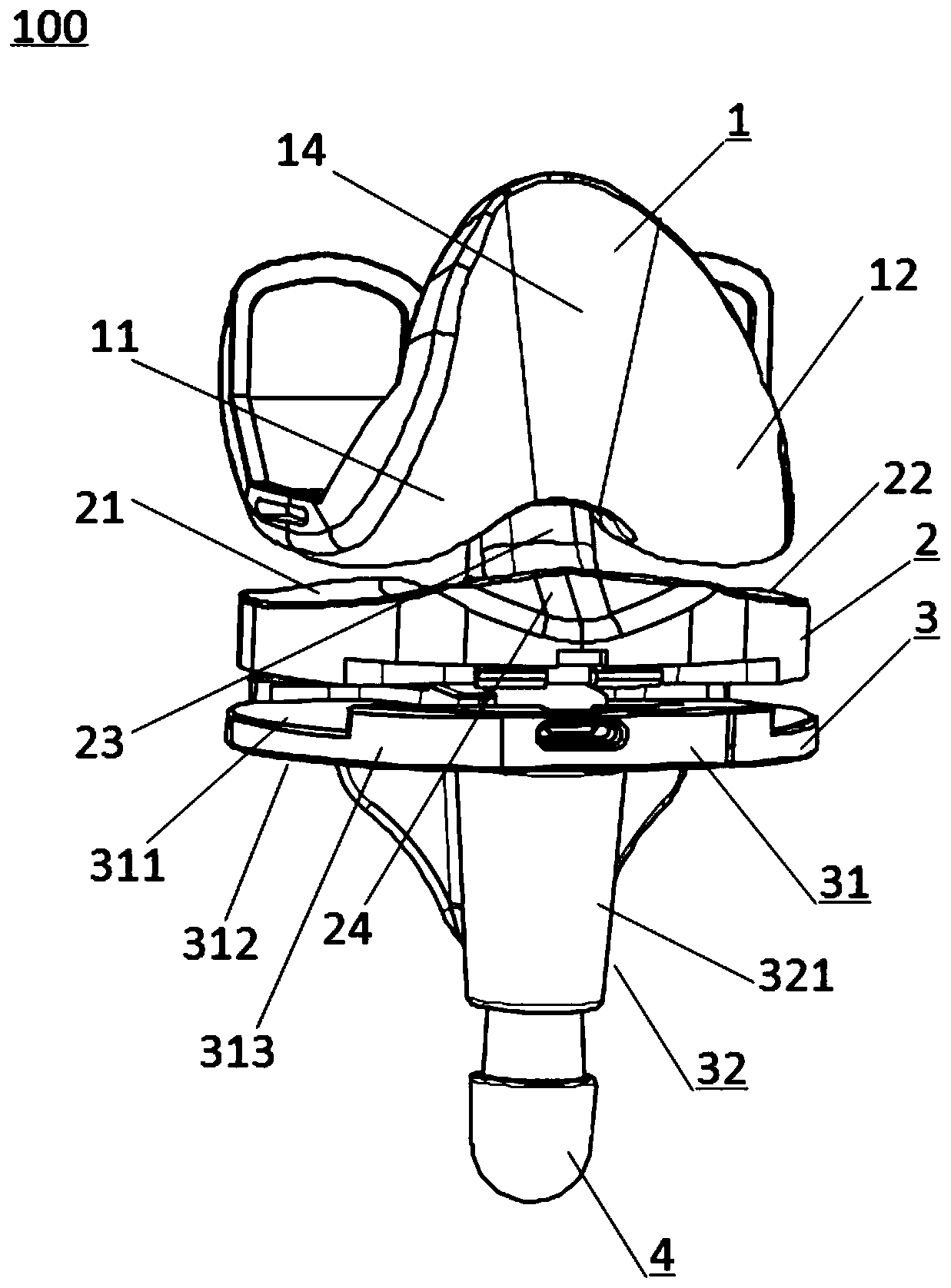
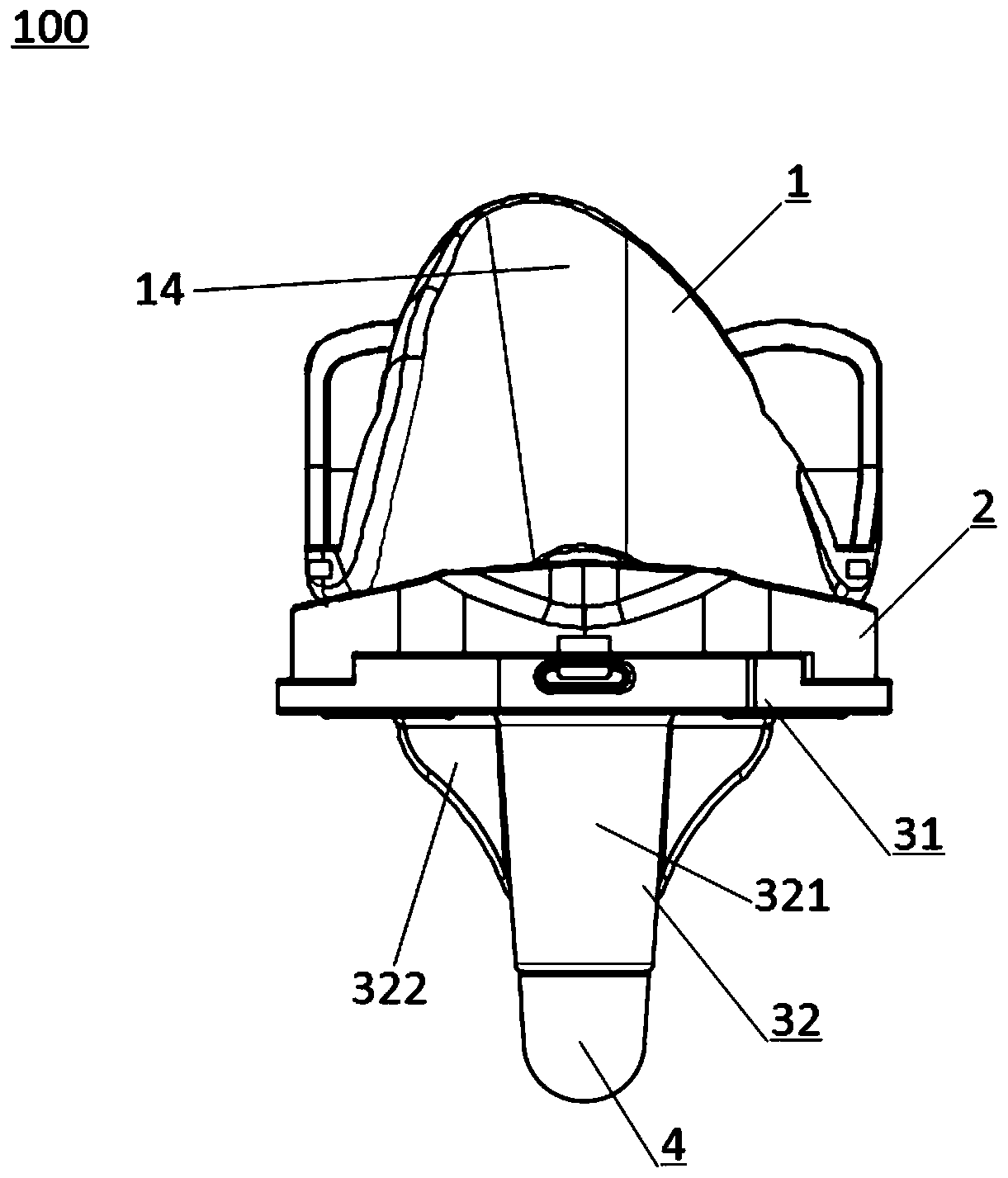
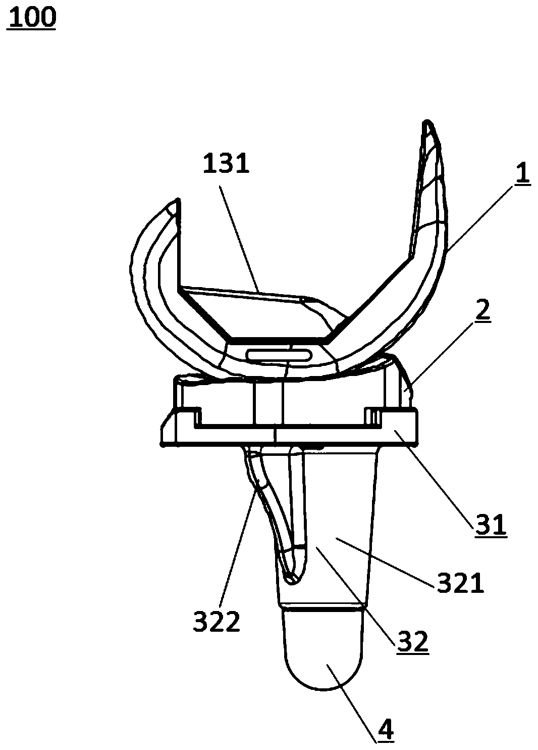
[0028] Figure 1 to Figure 3 The structure of the knee joint prosthesis 100 according to the embodiment of the present invention is shown. like Figure 1 to Figure 3 As shown, the knee joint prosthesis 100 includes a femoral prosthesis 1 and a tibial plateau liner 2 slidingly fitted with the femoral prosthesis 1, combined with Figure 4 As shown, the surface of the femoral prosthesis 1 that cooperates with the tibial plateau liner 2 is formed with an inner condyle surface 11 and an outer condyle surface 12, and an intercondylar channel formed between the inner condyle surface 11 and the outer condyle surface 12 13 and the intercondylar groove 14 that is connected with the intercondylar through groove 13 and extends along the length directio...


PUM


Abstract

The invention belongs to the technical field of medical prostheses, and discloses a knee joint prosthesis. The knee joint prosthesis comprises a femoral prosthesis and a tibia platform liner. The surface, matched with the tibia platform liner, of the femoral prosthesis is provided with a medial condyle surface, a lateral condyle surface, an intercondylar through groove formed between the medial condyle surface and the lateral condyle surface, and an intercondylar concave groove connected with the intercondylar through groove. The surface, matched with the femoral prosthesis, of the tibia platform liner is provided with a medial condyle support surface, a lateral condyle support surface for correspondingly supporting the medial condyle surface and the lateral condyle surface, a guide standcolumn formed between the medial condyle support surface and the lateral condyle support surface, and a convex part. The cross section of the intercondylar concave groove is of a fan-shaped structure,and the distance between the two side edges of the central angle of the fan-shaped structure is gradually increased in the direction away from the intercondylar through groove from the intercondylarthrough groove. The knee joint prosthesis can improve the stability of the prosthesis after implantation and can reduce the probability of pain caused by stimulation of surrounding soft tissues afterprosthesis implantation.

Description

technical field [0001] The invention belongs to the technical field of medical prosthesis, in particular to a knee joint prosthesis. Background technique [0002] A knee prosthesis is a surgical implant used to replace the knee joint. It is used in superficial knee replacement surgery of the knee to treat the damaged knee and replace it with a knee prosthesis. The existing knee joint prosthesis mainly includes: a femoral prosthesis for connecting with the femur of the human body, a tibial plateau support for connecting with the tibia of the human body, and a liner between the femoral prosthesis and the tibial plateau support. [0003] Currently, knee prostheses are widely used in joint replacement surgery. However, the knee joint prosthesis in the prior art usually has the following disadvantages: 1) The problem of prepatellar pain of the patella joint often occurs after the knee joint prosthesis is implanted. The reason for this is that the relative sliding between the fe...

Claims


Application Information

Patent Timeline
Patent Type & Authority Applications(China)
IPC IPC(8): A61F2/38
CPCA61F2/3859A61F2/3868A61F2002/30004A61F2002/30604A61F2002/3863
Inventor 史春宝解凤宝王帅
Owner BEIJING CHUNLIZHENGDA MEDICAL INSTR
Why Eureka
Try Eureka