
Fixation support for traumatic orthopedics

A technology of trauma orthopedics and fixation frame, which is applied in the field of trauma orthopedics fixation frame, can solve the problems of not having, not having effective clamping and fixing, and not having arc-shaped splint, so as to reduce labor intensity, improve disinfection effect and disinfection range full effect

Inactive Publication Date: 2020-07-14
庞晖
View PDF15 Cites 1 Cited by
  • Summary
  • Abstract
  • Description
  • Claims
  • Application Information

AI Technical Summary

Problems solved by technology

[0005] Aiming at the deficiencies of the prior art, the present invention provides a traumatic orthopedic fixation frame, which solves the problem that the existing traumatic orthopedic fixation frame does not have the ability to automatically move the liquid storage tank loaded with disinfectant to facilitate the fixation of the human body between the splints. There is no mechanism for disinfecting bone wounds in different positions of the arm, and there is no mechanism for medical staff to press and control the spraying of disinfectant on the wounded part of the patient. At the same time, there is no mechanism for adjusting the height of the arc-shaped splint 2 mechanism, and does not have the technical problem of effectively clamping and fixing the human arm between the first curved splint and the second curved splint

Method used


Image

  • Fixation support for traumatic orthopedics
  • Fixation support for traumatic orthopedics
  • Fixation support for traumatic orthopedics

Examples


Embodiment 1

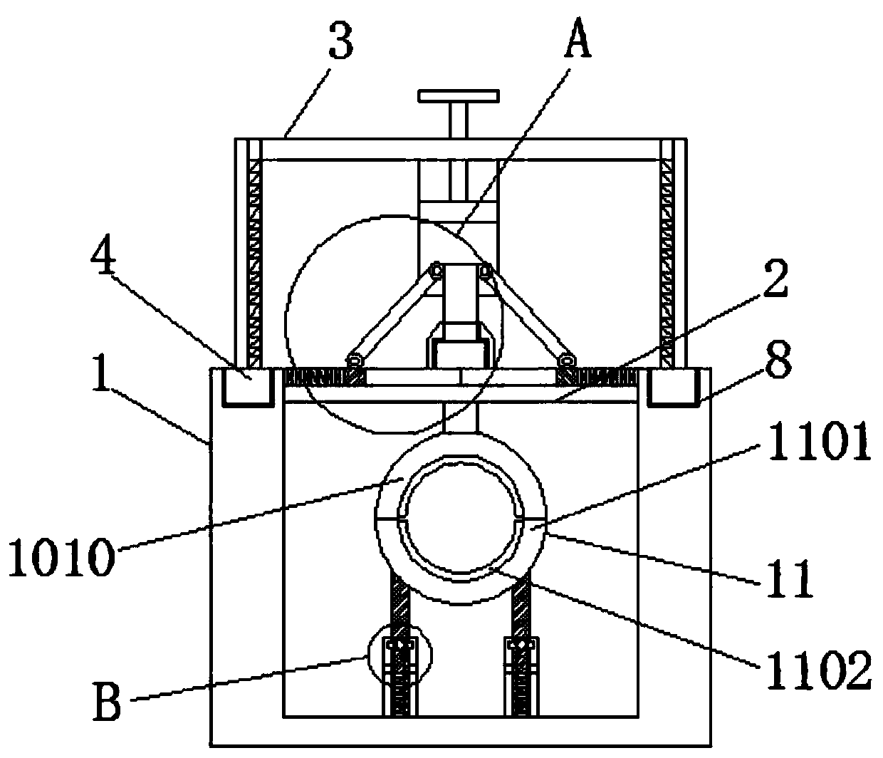
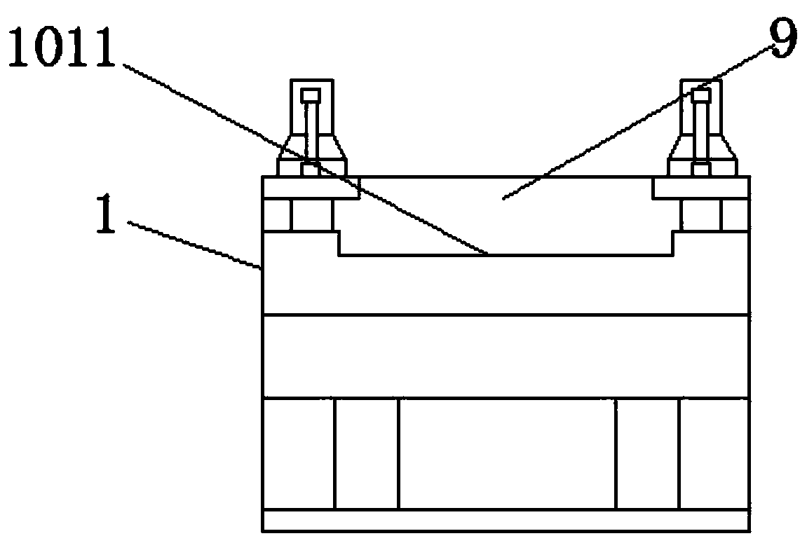
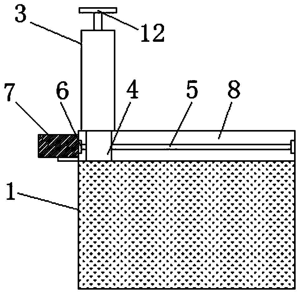
[0036] Embodiment 1: as figure 1 — Figure 6 , a traumatic orthopedic fixation frame, comprising: a U-shaped bracket 1, a horizontal plate 2, an n-shaped bracket 3, a first slider 4, an externally threaded shaft 5, a movable connector 6, a servo motor 7, a first chute 8, The first opening 9, the pressing mechanism 10, the second chute 1001, the second slider 1002, the first spring 1003, the first movable shaft 1004, the movable rod 1005, the second movable shaft 1006, the external threaded support rod 1007, the external Threaded port 1008, internal thread lock 1009, arc splint 1 1010, second opening 1011, lifting adjustment and fixing mechanism 11, arc splint 2 1101, arc cushion 1102, telescopic inner rod 1103, third slider 1104, Third chute 1105, fixed outer rod 1106, through groove 1107, second spring 1108, external threaded column 1109, hand screw 1110, pressing disinfection mechanism 12, liquid storage tank 1201, piston 1202, pressing T bar 1203, nozzle 1204 , spray hole...


PUM


Abstract

The invention provides a fixation support for traumatic orthopedics and relates to the technical field of fixation supports for traumatic orthopedics. The fixation support comprises a U-shaped bracket, wherein a cross plate is fixedly connected with the inner wall of the U-shaped bracket, and first chutes are formed in the top ends of the U-shaped bracket; first slide blocks are in sliding connection inside the first chutes; an n-shaped bracket is fixedly connected with the top ends of the first slide blocks; and an external threaded shaft is in threaded connection with the inner side of eachfirst slide block, and a movable connecting part is arranged outside each external threaded shaft in a sleeving manner. The fixation support has the beneficial effects that, when the n-type bracket isneeded to move for disinfecting the wound on a human arm by pressing a disinfection mechanism, the external threaded shafts can rotate along with the inside two movable connecting parts by starting an external power supply of a servo motor, the first slide blocks which are arranged outside the chutes and in threaded connection with the external threaded shafts can move on the first chutes which are formed in the top ends of the U-shaped bracket, and the n-shaped bracket can be moved automatically.

Description

technical field [0001] The invention relates to the technical field of traumatic orthopedic fixers, in particular to a traumatic orthopedic fixer. Background technique [0002] With the progress and development of the times, the medical equipment in today's era is constantly developing. To provide medical services to patients, people will inevitably encounter large and small bumps in their lives, and sometimes they will hurt the skin and bones. After the wound site is fixed, the drug treatment is carried out. [0003] The existing trauma orthopedic fixation frame does not have a mechanism that can automatically move the liquid storage tank loaded with disinfectant to facilitate disinfection of bone wounds in different positions of the human arm fixed between the splints, and does not have a mechanism that can facilitate medical treatment The mechanism for personnel to press and control the spraying of disinfectant on the wounded part of the patient does not have a mechanism...

Claims


Application Information

Patent Timeline
Patent Type & Authority Applications(China)
IPC IPC(8): A61F5/058A61M35/00A61F7/00
CPCA61F5/05858A61F7/007A61F2007/0029A61M35/00
Inventor 庞晖靳继海
Owner 庞晖
Learn More