
Winding head of spinning machine

A technology of machine winding and spinning, which is applied in the direction of conveying filamentous materials, thin material processing, transportation and packaging, etc. It can solve the problem of difficult control of the winding distance of silk thread and the tightness of silk winding, and achieve the effect of ensuring the winding quality

Pending Publication Date: 2020-07-14
光山县群力化纤有限公司
View PDF0 Cites 0 Cited by
  • Summary
  • Abstract
  • Description
  • Claims
  • Application Information

AI Technical Summary

Problems solved by technology

[0003] The purpose of the present invention is to overcome the deficiencies in the prior art, to solve or at least alleviate the problems that the existing telescopic winding mechanism is not easy to control the winding distance of the wire and the tightness of the wire winding, and to provide a spinning machine winding head

Method used


Image

  • Winding head of spinning machine
  • Winding head of spinning machine
  • Winding head of spinning machine

Examples


Embodiment 1

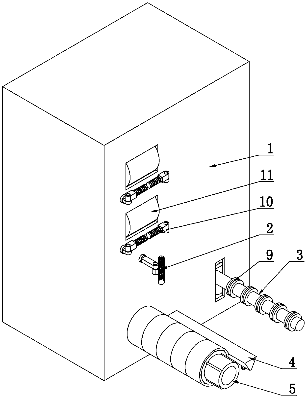
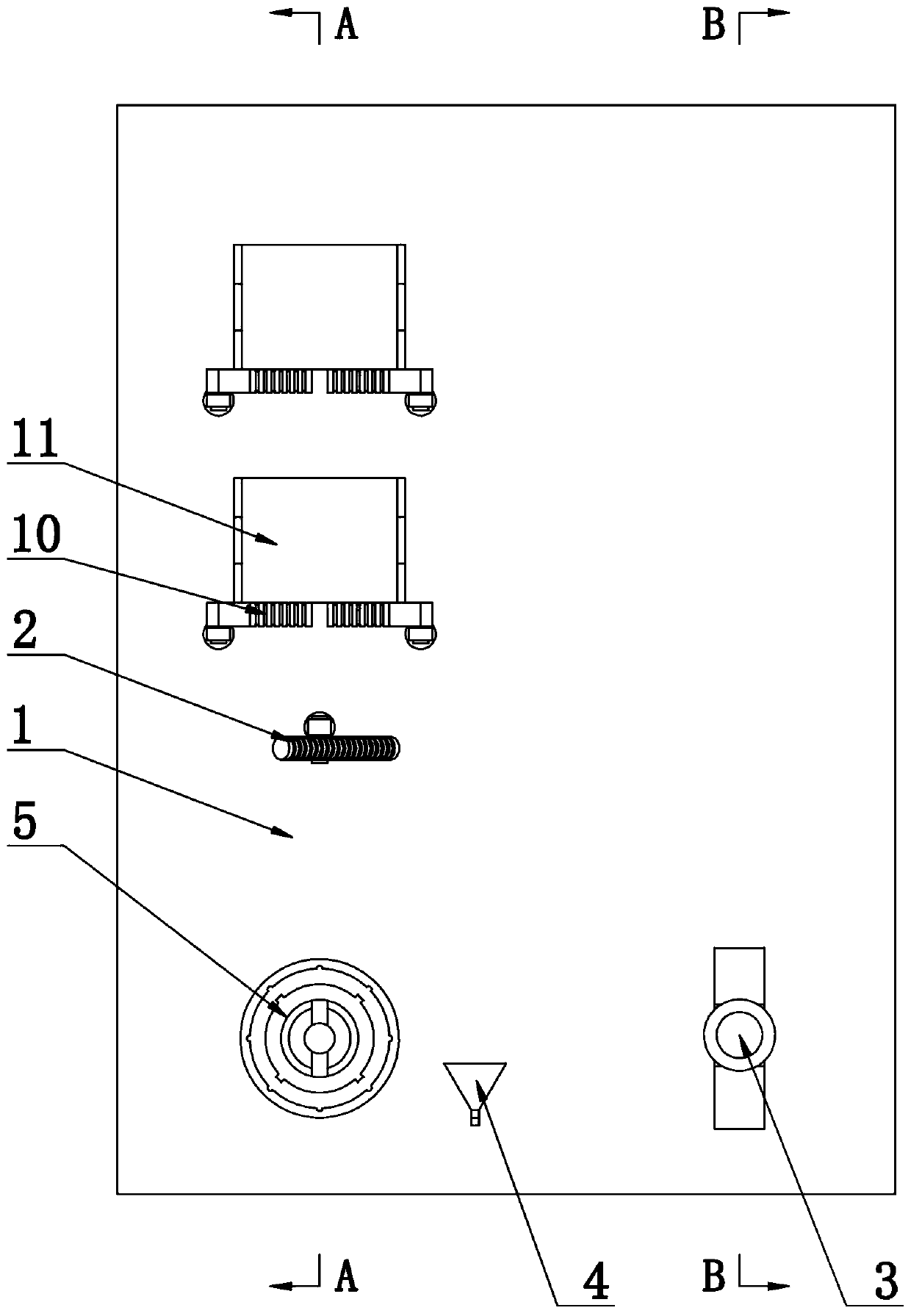
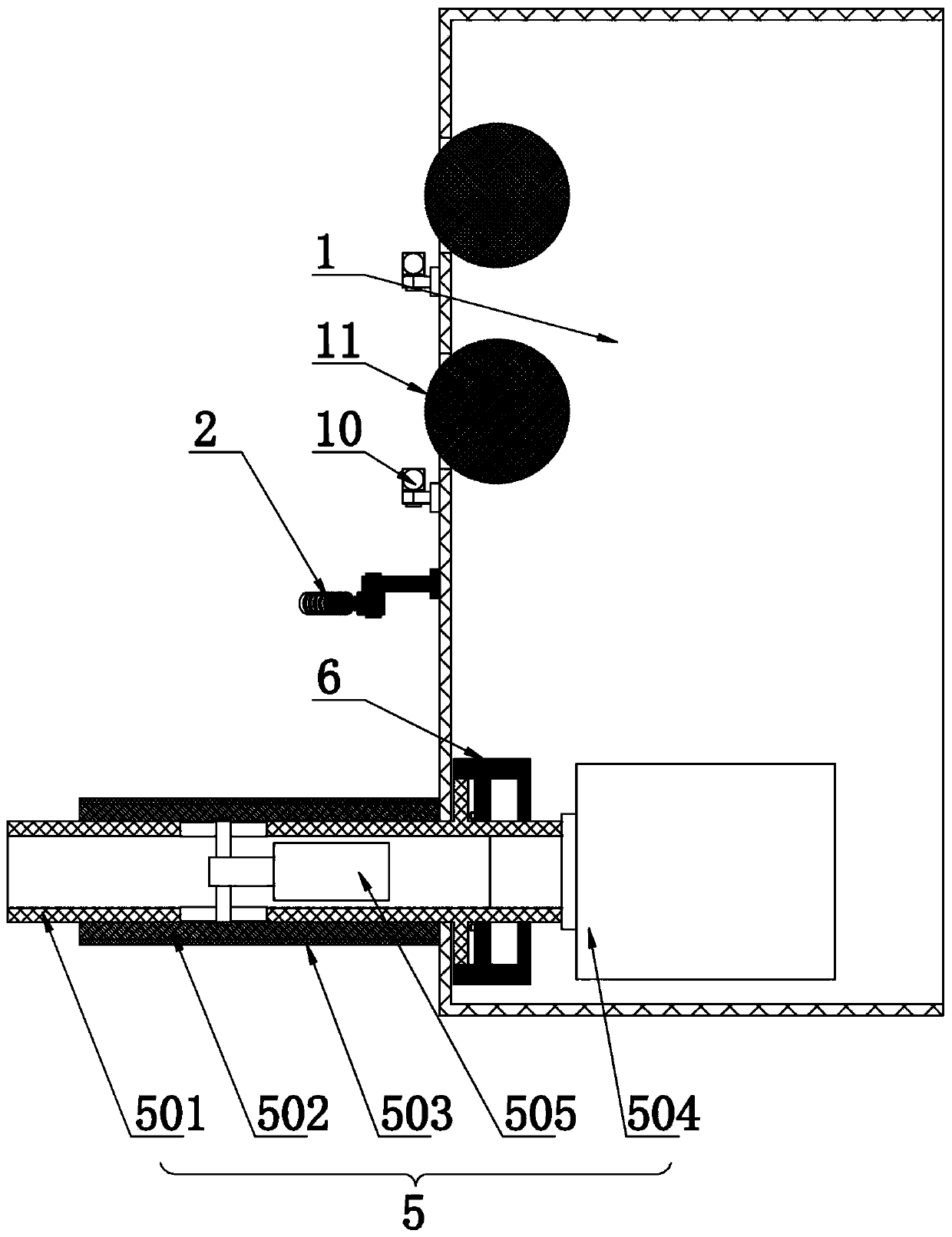
[0034] Such as Figure 1-11 As shown, a winding head of a spinning machine includes a box body 1, a steering rod 2, a guide rod 3, a positioning rod 4 and a winding drum 5, a steering rod 2, a guiding rod 3, a positioning rod 4 and a winding drum 5 They are all arranged on the end face of the box body 1, the winding drum 5 is located below the steering rod 2, the guide rod 3 and the positioning rod 4 are located on one side of the winding drum 5, and the winding drum 5 includes a rolling drum 501, a traverse drum 502, The fixed sleeve 503, the rotating motor 504 and the telescopic motor 505, the rolling cylinder 501, the traverse cylinder 502 and the fixed sleeve 503 are hollow cylinders coaxially fitted from the inside to the outside, one end of the rotating cylinder is rotationally connected with the box body 1, and the other end is extended. Out of the box 1, the traversing cylinder 502 slides and fits on the rolling cylinder 501 along the length direction of the rolling cy...


PUM


Abstract

The invention relates to a winding head of a spinning machine. The winding head comprises a box, a steering bar, a guide rod, a positioning rod and a winding drum. The winding drum comprises a rollingcylinder, a transverse moving cylinder, fixing sleeves, a rotary motor and a telescopic motor, wherein the rolling cylinder, the transverse moving cylinder and the fixing sleeves are in a hollow cylinder shape coaxially sleeved from inside to outside; one end of a rotary cylinder is rotationally connected with the box, the other end of the rotary cylinder extends out of the box, the transverse moving cylinder slidably sleeves the rolling cylinder in the length direction of the rolling cylinder, and the fixing sleeves slidably sleeve the transverse moving cylinder in the length direction of the transverse moving cylinder. The rotary motor is arranged in the box, a rotating shaft of the rotary motor is in transmission connection with the rolling cylinder, the telescopic motor is fixedly arranged in the rotary cylinder, and the end of a telescopic rod of the telescopic motor extends out of the circumferential side wall of the rotary cylinder and is fixedly connected with the transverse moving cylinder. The winding head aims to solve or at least alleviate the problem that the yarn winding distance and yarn winding tightness of an existing telescopic winding mechanism are not easy to control, and the winding head of the spinning machine is provided.

Description

technical field [0001] The invention relates to the technical field of textile equipment, in particular to a winding head of a spinning machine. Background technique [0002] After the synthetic fiber is spun and formed, the filament must be wound into a package with a certain shape and capacity according to certain rules, and the short fiber must be placed in a barrel in an orderly manner, so as to be transported to the next process for further processing, or The coils of semi-finished products are used by external factories, and the drafting and winding device is the key. With the continuous expansion of the chemical fiber market, the competition among manufacturers is becoming increasingly fierce, but the winding mechanism and the telescopic mechanism of the draft winding device of the existing spinning machine are two independent mechanisms and there is a certain distance between them. , when winding, it is easy to have a large winding distance or thread pressing phenom...

Claims


Application Information

Patent Timeline
Patent Type & Authority Applications(China)
IPC IPC(8): B65H54/547B65H54/44B65H54/70B65H59/10B65H59/36
CPCB65H54/547B65H54/44B65H54/70B65H59/10B65H59/36B65H2701/31
Inventor 祝晓曦许太厚
Owner 光山县群力化纤有限公司
Learn More