
Steel beam-concrete composite floor slab combined assembly system

A technology of superimposing floor slabs and combined assembly, which is applied in the direction of slabs, building components, buildings, etc., which can solve the problem that the design calculation is not calculated according to the method of composite structure, the strength of steel is not fully exerted, and it does not meet the damage of strong columns and weak beams, etc. problems, to avoid excessive concrete, light weight, and shorten the construction period.

Inactive Publication Date: 2020-07-14
BEIJING UNIV OF TECH
View PDF13 Cites 4 Cited by
  • Summary
  • Abstract
  • Description
  • Claims
  • Application Information

AI Technical Summary

Problems solved by technology

In addition, before the combination effect is formed, the beams already have deflection under the floor's own weight, which causes the deflection of the beams and the floor to increase, and the deflection of the steel structure often reaches the specification limit, so that the strength of the steel cannot be fully exerted
Generally, when designing the main girder, the design calculation is not calculated according to the method of composite structure, but the main girder and the floor have a certain combination effect, which leads to the fact that although the design is based on the principle of strong columns and weak beams when an earthquake occurs, the Due to the combination of the floor and the main beam, the actual damage does not conform to the damage of strong columns and weak beams
The beam-column connection is a welded connection. When the beam-column of the welded connection is damaged, a plastic hinge will be generated at the beam-column connection, which is easy to damage and will pollute the air.
However, the ordinary prefabricated structural system also has some shortcomings: only individual beams, slabs, and columns are prefabricated, and many small connectors of the components are prepared on site, causing confusion on the construction site

Method used


Image

  • Steel beam-concrete composite floor slab combined assembly system
  • Steel beam-concrete composite floor slab combined assembly system
  • Steel beam-concrete composite floor slab combined assembly system

Examples


Embodiment Construction

[0054] In order to make the purpose, technical solutions and advantages of the embodiments of the present invention clearer, the technical solutions in the embodiments of the present invention will be clearly and completely described below in conjunction with the drawings in the embodiments of the present invention. Obviously, the described embodiments It is a part of embodiments of the present invention, but not all embodiments. Based on the embodiments of the present invention, all other embodiments obtained by persons of ordinary skill in the art without making creative efforts belong to the protection scope of the present invention.

[0055] In the description of the present invention, it should be noted that the terms "center", "upper", "lower", "left", "right", "vertical", "horizontal", "inner", "outer" etc. The indicated orientation or positional relationship is based on the orientation or positional relationship shown in the drawings, and is only for the convenience of...


PUM


Abstract

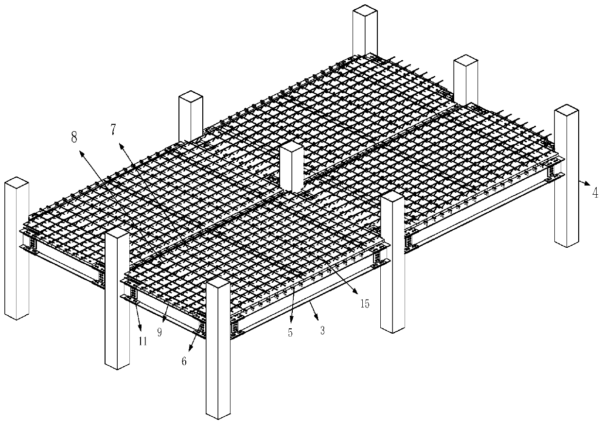
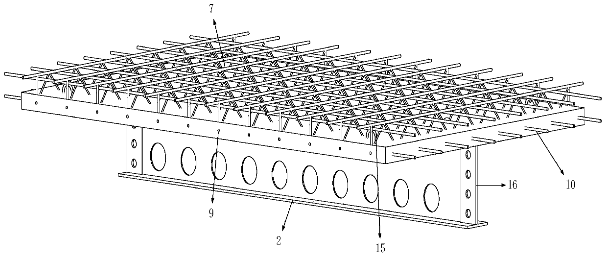
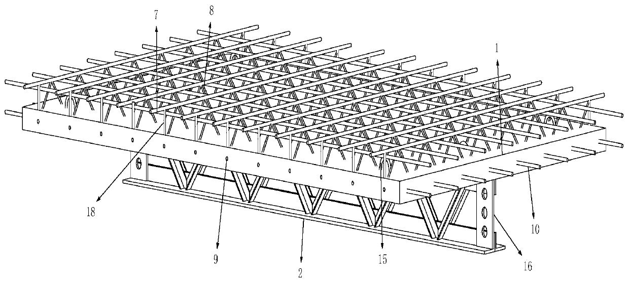
The invention discloses a steel beam-concrete composite floor slab combined assembly system. The steel beam-concrete composite floor slab combined assembly system comprises truss floors, a secondary beam and a primary beam, wherein the multiple truss floors are built onto a main framework formed by the primary beam; a first fixed connector which is connected to the truss floors is arranged on theprimary beam; the secondary beam is fixedly arranged below the truss floors; a second fixed connector which is connected to the truss floors is arranged on the secondary beam; the two ends of the secondary beam are provided with connecting plates; and the secondary beam is connected to the primary beam through the connecting plates. According to the steel beam-concrete composite floor slab combined assembly system disclosed by the invention, the truss floors, the secondary beam and the primary beam are prefabricated together at a plant, so that the initial deflection problem, caused by wet concrete if the concrete is poured on a site, of floors and the beams is avoided, and therefore, the purpose of increasing floor strength and rigidity is achieved; and meanwhile, the assembly system alsocan greatly shorten the construction period, and improves construction efficiency.

Description

technical field [0001] The invention belongs to the technical field of assembled prefabricated floor slab structures, in particular to a steel beam-concrete composite floor slab assembly system. Background technique [0002] The traditional building construction method is the pouring-in-site construction mode, that is, the operation mode from erecting scaffolding, setting up formwork, binding steel bars to pouring concrete on site. On-site pouring construction produces a lot of dust, noise, sewage, etc. during the construction process, and the construction speed is slow, the construction intensity is high, and it is greatly affected by seasonal climate. Therefore, in recent years, my country has been continuously promoting the application of prefabricated buildings. The prefabricated building is based on the prefabricated production of component factories and on-site assembly installation. It is characterized by standardized design, factory production, assembly construction...

Claims


Application Information

Patent Timeline
Patent Type & Authority Applications(China)
IPC IPC(8): E04B5/17
CPCE04B5/17
Inventor 刘学春朱雅楠邓玉萍黎佺炜
Owner BEIJING UNIV OF TECH
Learn More