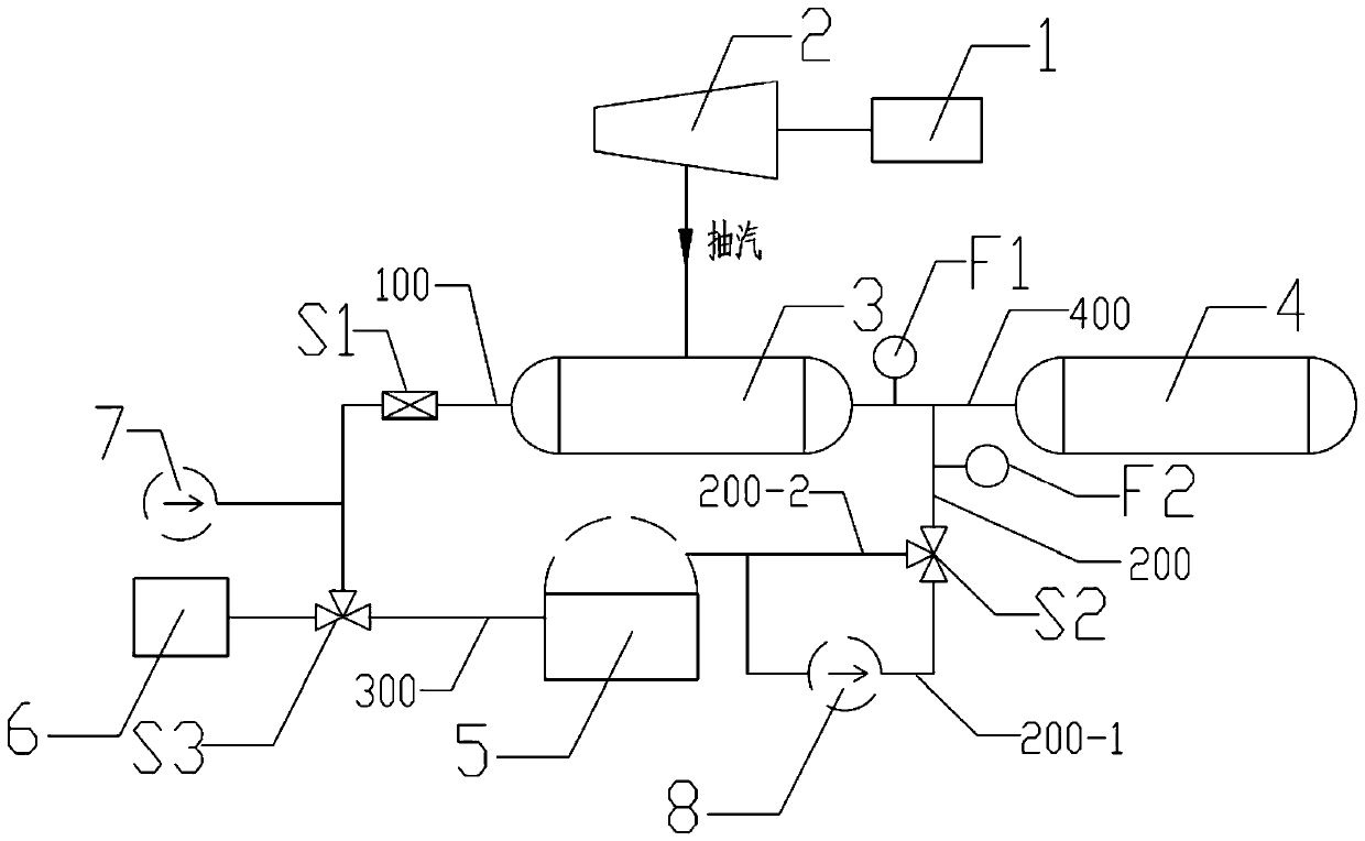
Power control method of heat storage peak shaving system under heat storage and heat release working conditions

A power control and peak shaving technology, which is applied in the direction of control of water supply, separation methods, chemical instruments and methods, etc., can solve the problems of water level disturbance of deaerator, increase of unit output, fluctuation of main steam pressure, etc., and achieve the goal of increasing the climbing rate Effect

Pending Publication Date: 2020-07-14
NORTH CHINA POWER ENG
View PDF0 Cites 0 Cited by
  • Summary
  • Abstract
  • Description
  • Claims
  • Application Information

AI Technical Summary

Problems solved by technology

[0004] Although the use of boiler heat storage capacity can quickly respond to dispatching instructions, the heat storage capacity is limited, which can only increase the output of the unit in the short term, and cause large fluctuations in the main steam pressure
The optimization method of condensate throttling reduces the flow rate of the condensate regulating valve and relies on the self-balancing

Method used


Image

  • Power control method of heat storage peak shaving system under heat storage and heat release working conditions
  • Power control method of heat storage peak shaving system under heat storage and heat release working conditions
  • Power control method of heat storage peak shaving system under heat storage and heat release working conditions

Examples


Embodiment Construction

[0037]The following will clearly and completely describe the technical solutions in the embodiments of the present invention with reference to the accompanying drawings in the embodiments of the present invention. Obviously, the described embodiments are only some of the embodiments of the present invention, not all of them. Based on the embodiments of the present invention, all other embodiments obtained by persons of ordinary skill in the art without making creative efforts belong to the protection scope of the present invention.

[0038] At first introduce relevant terms among the present invention:

[0039] Unit adjustment rate: the power that the unit can increase or decrease per minute, unit MW / min.

[0040] Coordinated control system of the unit: take the boiler and steam turbine of the unit as the controlled objects, and make the two coordinate and cooperate to control the change of the generating power of the unit.

[0041] Load command: issued by the unit coordinati...


PUM


Abstract

The invention provides a power control method of a heat storage peak shaving system under heat storage and heat release working conditions. The heat storage peak shaving system is included. In a heatstorage mode, after condensed water (cold water) sent out by a condensed water pump passes through a heater, the cold water is changed into hot water, one path of hot water enters a deaerator, the other path of hot water enters a water storage tank, and the equal amount of cold water is discharged to a condenser from the water storage tank. Due to the fact that the total amount of hot water entering the deaerator is relatively fixed, the flow entering the water storage tank is increased, the flow passing through the heater is also increased, the generating power of a unit is reduced, and viceversa. In a heat release mode, one path of condensed water sent out by the condensed water pump passes through the heater to enter the deaerator, the other path of the condensed water sent out by thecondensed water pump enters the water storage tank, and the equal amount of hot water is pumped to the deaerator from the water storage tank through a booster pump. Due to the fact that the total amount of hot water entering the deaerator is relatively fixed, the flow pumped out of the water storage tank is increased, the flow passing through the heater is reduced, the generating power of the unitis increased, and vice versa. An applicant proposes a heat storage technology by using the water storage tank, the ramp rate of the unit is increased, a power grid dispatching instruction is rapidlyresponded, and the power control method of the heat storage peak shaving system under heat storage and heat release working conditions is a new mode for increasing the ramp rate of the unit.

Description

technical field [0001] The invention designs the field of thermal power generation technology peak regulation, and specifically relates to a heat storage peak regulation system and a control method thereof. Background technique [0002] In order to meet the needs of the rapid development of renewable energy and improve the capacity of renewable energy consumption, it is urgent to improve the flexibility of the power grid. Among them, the flexibility of load adjustment includes: deep peak shaving (low load operation of boiler and steam turbine), rapid start and stop of units, ramp rate of units, and thermoelectric decoupling of combined heat and power units. [0003] At present, the rapid adjustment of the power generation of the unit mainly uses the steam inlet valve of the steam turbine to release the heat storage capacity of the boiler in the short term; the condensate throttling optimization method changes the condensate flow through the heater in a short time. [0004] ...

Claims


Application Information

Patent Timeline
IPC IPC(8): F22D1/50F22D3/04F22D5/26F28B9/08
CPCF22D1/50F22D3/04F22D5/26F28B9/08
Inventor 杨鹏远王秋瑾吴展刘巧红贾静宋昉唐海峰钟文英
Owner NORTH CHINA POWER ENG
Why Eureka
Try Eureka