A Dynamic Sealed Calorimeter with Fault Tolerant Structure

A technology of dynamic sealing and calorimeter, applied in the field of teaching instruments, can solve the problems of unaligned, unreasonable structural design, and poor sealing of the inner cylinder or outer cylinder, so as to achieve no principle error, good dynamic sealing, Easy and fast operation

Active Publication Date: 2020-12-22
南京捷天信息技术有限公司
View PDF1 Cites 0 Cited by
  • Summary
  • Abstract
  • Description
  • Claims
  • Application Information

AI Technical Summary

Problems solved by technology

The problem with this calorimeter is that the rubber cover 6 needs to be in contact with the upper edge of the outer cylinder 1 and the inner cylinder 2 at the same time to ensure the seal, which is unreasonable in the structural design. In fact, due to manufacturing accuracy and thermal expansion, it is difficult to Ensure that the upper edges of the outer cylinder 1 and the inner cylinder 2 are in close contact with the corresponding parts of the rubber cover 6. One of the outer cylinder 1 and the inner cylinder 2 must not be tightly closed. This is an important reason why it is difficult to ensure the sealing of the calorimeter
This calorimeter solves the problem of heat exchange between the agitator socket and the thermometer socket and the outside world, but there are still (1) it is difficult to ensure that the sealing ring in contact with the inner cylinder or the upper edge of the outer cylinder is completely closed. Even if the quality is uniform, the inlays are evenly made, and the height is consistent, it will still cause one of the inner cylinder or the outer cylinder to be closed tightly; Along the alignment, in some experiments such as the "mixing method to measure the specific heat capacity of metals" experiment, the metal block of the substance to be tested will generally reach equilibrium within a few seconds after being placed in the inner cylinder, and this device cannot complete the measurement work

Method used


Image

  • A Dynamic Sealed Calorimeter with Fault Tolerant Structure
  • A Dynamic Sealed Calorimeter with Fault Tolerant Structure
  • A Dynamic Sealed Calorimeter with Fault Tolerant Structure

Examples


Embodiment Construction

[0021] The preferred embodiments of the present invention will be described below in conjunction with the accompanying drawings. It should be understood that the preferred embodiments described here are only used to illustrate and explain the present invention, and are not intended to limit the present invention.

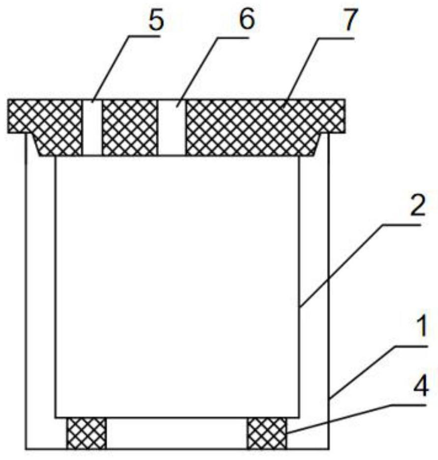
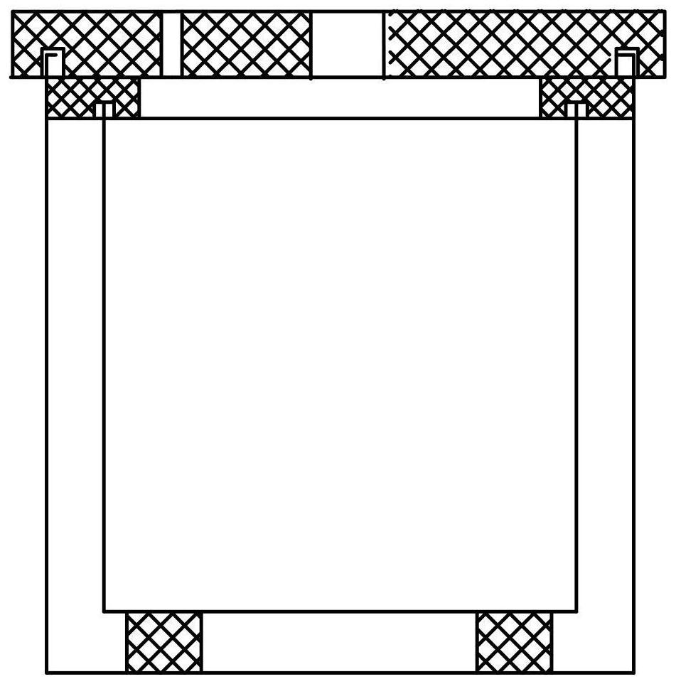
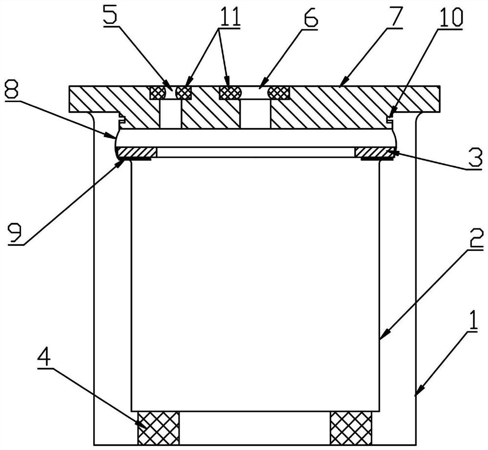
[0022] A dynamic hermetic calorimeter with a fault-tolerant structure such as image 3 As shown, it includes: outer cylinder 1, inner cylinder 2, rubber ring 3, gasket 4, agitator jack 5, thermometer jack 6, rubber cover 7, sealing cylinder 8, soft rubber pad 9, ring groove 10, small seal Ring 11; the outer cylinder 1 and the inner cylinder 2 are metal cylinders with closed bottom ends, the upper edge of the mouth of the cylinder is made into an arc shape outward, and the inner cylinder 2 is placed at the bottom of the outer cylinder 1 through a heat-insulating gasket 4 , There is a uniform gap between the inner cylinder 2 and the outer cylinder 1.

[0023] The rub...


PUM


Abstract

The invention provides a dynamic sealing calorimeter with a fault-tolerant structure. The upper part of a rubber cover (7) is a larger cylinder, and an annular groove (10) is formed in the upper partof the smaller cylinder at the lower part; a sealing cylinder (8) is a thin-wall cylinder made of a soft rubber material, the upper end is tightly sleeved on the lower cylinder of the rubber cover (7)and is embedded into the annular groove (10), the middle part is slightly in a waist drum shape, the lower end is connected with a rubber ring (3), and a soft rubber pad (9) is attached to the bottomsurface of the rubber ring (3); when the rubber cover (7) covers the outer cylinder (1), the sealing cylinder (8) drives the rubber ring (3) and the soft rubber pad (9) to press the arc edge of the upper edge of an inner cylinder (2), so that the inner cylinder (2) is sealed, and the upper edge of the outer cylinder is directly contacted with the rubber cover 7, and a stagnant layer of air is formed in the middle of the outer cylinder 1 and the inner cylinder 2. The calorimeter has no structural design defect, and can keep no heat exchange between the system and the outside in the dynamic measurement work.

Description

technical field [0001] The invention relates to a teaching instrument, in particular to a calorimeter which has a fault-tolerant structure and can be kept sealed during dynamic work. Background technique [0002] A calorimeter is an insulated device used to measure changes in heat within a system. Calorimeters commonly used in physical experiments such as figure 1 As shown: the outer cylinder 1 and the inner cylinder 2 are directly in contact with the rubber cover 7 for sealing, and a stagnant air layer is formed between the outer cylinder 1 and the inner cylinder 2 to reduce heat conduction with the outside. The rubber cover 6 is equipped with a stirrer insert Hole 5 and thermometer jack 6. The problem with this calorimeter is that the rubber cover 6 needs to be in contact with the upper edge of the outer cylinder 1 and the inner cylinder 2 at the same time to ensure the seal, which is unreasonable in the structural design. In fact, due to manufacturing accuracy and therm...

Claims


Application Information

Patent Timeline
Patent Type & Authority Patents(China)
IPC IPC(8): G01K17/00G09B23/16F16J15/10
CPCF16J15/104G01K17/00G09B23/16
Inventor 徐燕张晓英黄年伟高梓晗戴本书
Owner 南京捷天信息技术有限公司
Why Eureka
Try Eureka