Antenna test system and test method

A technology for testing systems and antennas, applied in antenna radiation patterns, measuring devices, and measuring electrical variables. It can solve problems such as poor stability, inability to freely change beam angles, and low test efficiency, so as to improve efficiency and stability, and shorten construction time. Cycle time and the effect of saving construction costs

Pending Publication Date: 2020-07-14
NANJING JIEXI TECH
View PDF0 Cites 4 Cited by
  • Summary
  • Abstract
  • Description
  • Claims
  • Application Information

AI Technical Summary

Problems solved by technology

[0004] In order to solve the technical problems of low test efficiency, poor stability and inability to freely change the beam angle in the existing passive antenna test technology, the present invention provides an antenna test system and test method

Method used


Image

  • Antenna test system and test method
  • Antenna test system and test method
  • Antenna test system and test method

Examples


Embodiment 1

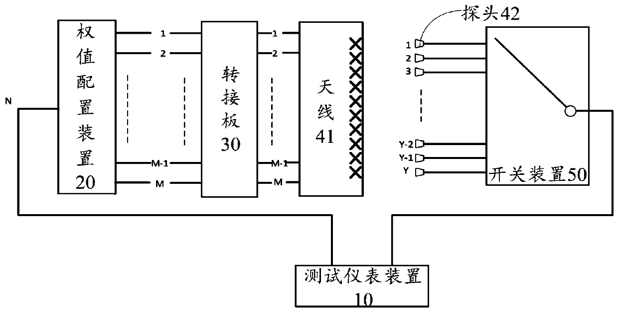
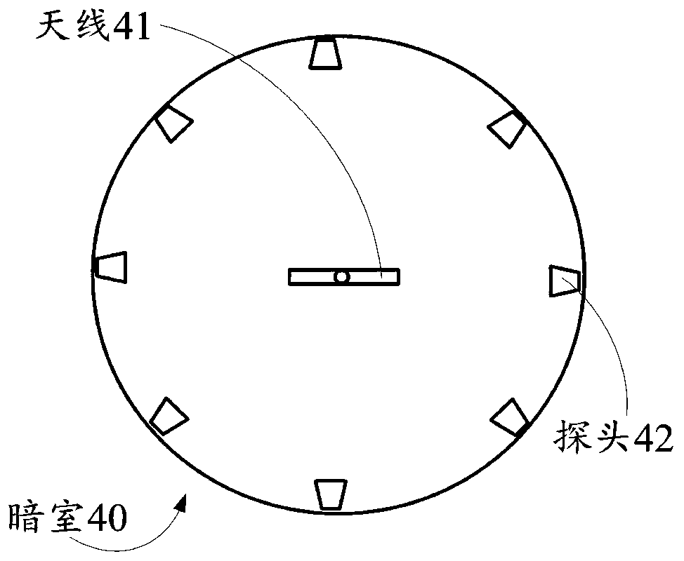
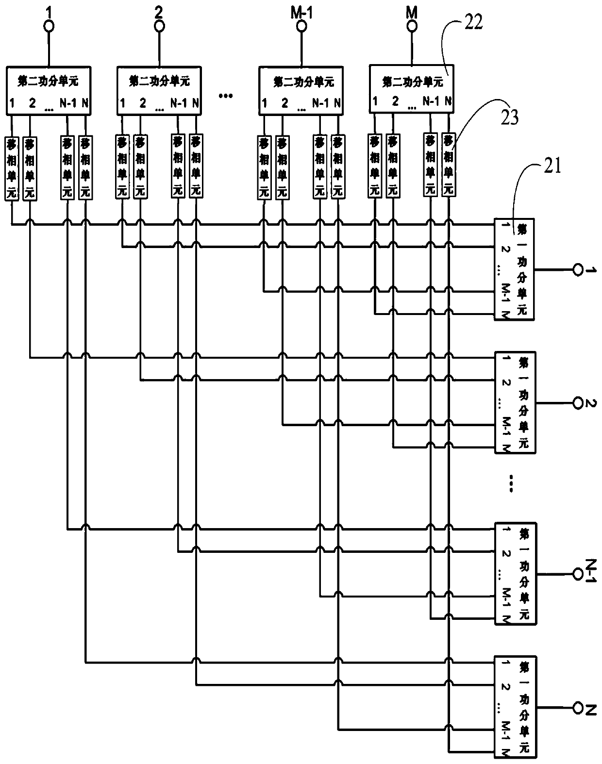
[0044] combine figure 1 with figure 2As shown, the antenna test system provided in Embodiment 1 includes a test instrument device 10, a weight configuration device 20, and a darkroom 40 for placing an antenna 41. The weight configuration device 20 includes a radio frequency matrix and a control module, and the control module and The radio frequency matrix is ​​connected, the test instrument device 10 is connected with the radio frequency matrix, and the radio frequency matrix is ​​used to connect with the antenna 41, and the darkroom 40 is provided with a probe 42, and the probe 42 is connected with the test instrument device 10; the control module is used to adjust the weight parameter of the radio frequency matrix To the target parameter, the test instrument device 10 is used to send the first signal to the radio frequency matrix, and the radio frequency matrix is ​​used to generate a second signal according to the weight parameter adjusted by the first signal and the contr...

Embodiment 2

[0069] combine Figure 9 As shown, Embodiment 2 provides an antenna test method, which is applied to the antenna test system in Embodiment 1, including:

[0070] Step S101: placing the antenna 41 in the darkroom 40;

[0071] Step S102: Initialize the antenna testing system;

[0072] Step S103: adjusting the weight parameter of the radio frequency matrix of the weight configuration device 20 to the target parameter;

[0073] Step S104: Control the test instrument device 10 to send the first signal to the radio frequency matrix, so that the radio frequency matrix generates a second signal according to the first signal and the adjusted weight parameter, and sends the second signal to the antenna 41, and the antenna 41 according to the first signal The second signal generates a third signal and sends the third signal to the probe 42, and the probe 42 sends the third signal to the test instrument device 10;

[0074] Step S105: return to the step of adjusting the weight parameter...


PUM


Abstract

In order to solve the technical problems of low test efficiency, poor stability and incapability of freely changing a beam angle in an existing passive antenna test technology. The invention providesan antenna test system and a test method. The antenna test system comprises a test instrument device, a weight configuration device and a darkroom for placing an antenna, wherein the weight configuration device comprises a radio frequency matrix and a control module, the control module is connected with the radio frequency matrix, the test instrument device is connected with the radio frequency matrix, the radio frequency matrix is used for being connected with the antenna, the darkroom is provided with a probe, and the probe is connected with the test instrument device. According to the method disclosed in the invention, the beam angle of the third signal can be adjusted only by adjusting the weight parameter of the weight configuration device without changing the hardware structure in use, and therefore the efficiency and stability of antenna testing are improved; the weight parameter can be flexibly and freely adjusted, and therefore the beam angle of the third signal can be freelychanged.

Description

technical field [0001] The invention relates to the field of communication technology testing, in particular to an antenna testing system and testing method. Background technique [0002] With the continuous development of 5G, the antenna test closely connected with the 5G radio frequency unit is becoming more and more important. The current test of 5G passive antennas is mostly connected by power splitter boards. During the test, different power splitter boards are replaced according to different weights, which makes the test efficiency low, poor stability, and the beam angle cannot be freely changed. Global antenna equipment manufacturers urgently need a complete, reliable and efficient passive antenna test system. [0003] Therefore, it is necessary to provide a solution to solve the technical problems of low test efficiency, poor stability and inability to freely change the beam angle in the existing passive antenna test technology. Contents of the invention [0004]...

Claims


Application Information

Patent Timeline
Patent Type & Authority Applications(China)
IPC IPC(8): G01R29/10G01R29/08
CPCG01R29/0871G01R29/105
Inventor 曹宝华其他发明人请求不公开姓名
Owner NANJING JIEXI TECH
Why Eureka
Try Eureka