Wafer heating device
A technology for heating devices and wafers, which is applied in the fields of electrical components, semiconductor/solid-state device manufacturing, circuits, etc. It can solve the problems of poor uniformity of wafer heating methods, and achieve the effect of meeting processing requirements and uniform temperature
- Summary
- Abstract
- Description
- Claims
- Application Information
AI Technical Summary
Problems solved by technology
Method used
Image

Examples
Embodiment 1
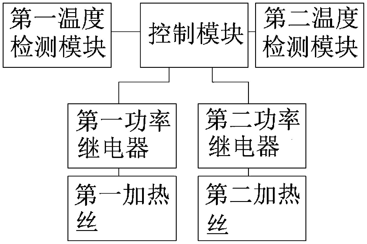
[0027] Such as figure 1 As shown, the wafer heating device includes a control module and a multi-zone hot plate. Those skilled in the art can divide the hot plate into several zones according to actual needs. For the convenience of illustration, this embodiment divides the multi-zone hot plate into the first Partition and Second Partition.
[0028] The first partition includes a first heating module and a first temperature detection module, the first temperature detection module is used to detect the temperature value of the first partition, and sends the detected temperature value of the first partition to the control module, and the first heating module uses for heating the first zone;
[0029] The second partition includes a second heating module and a second temperature detection module, the second temperature detection module is used to detect the temperature value of the second partition, and sends the detected temperature value of the second partition to the control mo...
Embodiment 2
[0041] The difference between this implementation and Example 1 is that the wafer heating is in the heating and heating stage. In this stage, the precision value of the control module is set to 0.5°C. When the temperature value difference between the first partition and the second partition exceeds 0.5°C , the control module reduces the output power of the power relay of the zone with higher temperature, or the control module increases the output power of the power relay of the zone with lower temperature.
[0042] A person skilled in the art can set the precision value of this stage according to actual needs.
[0043] Through the partitioned temperature management of the hot plate, the temperature difference between the various partitions is always within a reasonable range, and the heating rate can be increased, without worrying about the uneven temperature of the hot plate and damaging the wafer, and finally achieved the shortening of the wafer. Processing time, the purpose...
Embodiment 3
[0045] The difference between this implementation and Example 1 is that the wafer heating is in the cooling and cooling stage. In this stage, the precision value of the control module is set to 0.4°C. When the temperature value difference between the first partition and the second partition exceeds 0.4°C , the control module reduces the output power of the power relay of the zone with higher temperature, or the control module increases the output power of the power relay of the zone with lower temperature.
[0046] A person skilled in the art can set the precision value of this stage according to actual needs.
PUM
 Abstract
Description
Claims
Application Information
 - R&D
- Intellectual Property
- Life Sciences
- Materials
- Tech Scout
- Unparalleled Data Quality
- Higher Quality Content
- 60% Fewer Hallucinations
Browse by: Latest US Patents, China's latest patents, Technical Efficacy Thesaurus, Application Domain, Technology Topic, Popular Technical Reports.
© 2025 PatSnap. All rights reserved.Legal|Privacy policy|Modern Slavery Act Transparency Statement|Sitemap|About US| Contact US: help@patsnap.com