A communication equipment power supply system and its control method
A technology of communication equipment and power supply system, which is applied in the direction of control/regulation system, electrical components, circuit devices, etc., and can solve the problems that the power supply system cannot realize the proportion allocation requirements of the power supply link, the power supply of communication equipment is inflexible, and the efficiency of the power supply system is low. , to achieve the effect of improving maintainability, saving power consumption, and increasing the load rate of power supply
- Summary
- Abstract
- Description
- Claims
- Application Information
AI Technical Summary
Problems solved by technology
Method used
Image
Examples
Embodiment 1
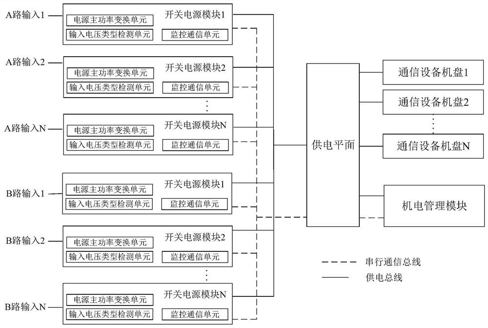
[0055] Such as figure 1 As shown in , it is a schematic structural diagram of a communication device power supply system provided by an embodiment of the present invention. The power supply system includes an electromechanical management module, a power supply plane, and at least 2N switching power supply modules (N≥1).
[0056] Wherein, the number of switching power supply modules input by the A channel is equal to the number of switching power supply modules input by the B channel.
[0057] The DC outputs of the N switching power supply modules input by the A channel are connected to the power supply plane, and the N switching power supply modules input by the A channel are connected by serial communication signals.
[0058] The DC outputs of the N switching power supply modules input by the B-channel are connected to the power supply plane, and the N switching power supply modules input by the B-channel are connected by serial communication signals.
[0059] The DC output...
Embodiment 2
[0074] This embodiment provides a solution for the electromechanical management module to determine the load distribution plan of each switching power supply module according to the operating status, input voltage type and physical slot information of each switching power supply module, specifically:
[0075] The calculation relationship of the distribution ratio of the power supply system undertaken by the input power of the A line and the B line is as follows:
[0076] D. A ﹦﹙N﹣M A ﹚ / ﹝2N﹣(M A +M B )﹞;
[0077] D. B ﹦﹙N﹣M B ﹚ / ﹝2N﹣(M A +M B )﹞;
[0078] In the formula, D A 、D B Respectively, the ratio of the power supply of the input power supply of the A channel and the B channel;
[0079] N is the number of normal operation of the switch modules configured in the power supply system detected by the electromechanical management module;
[0080] m A , M B are respectively the number of normal operating switching power supply modules whose A-way and B-way inputs a...
Embodiment 3
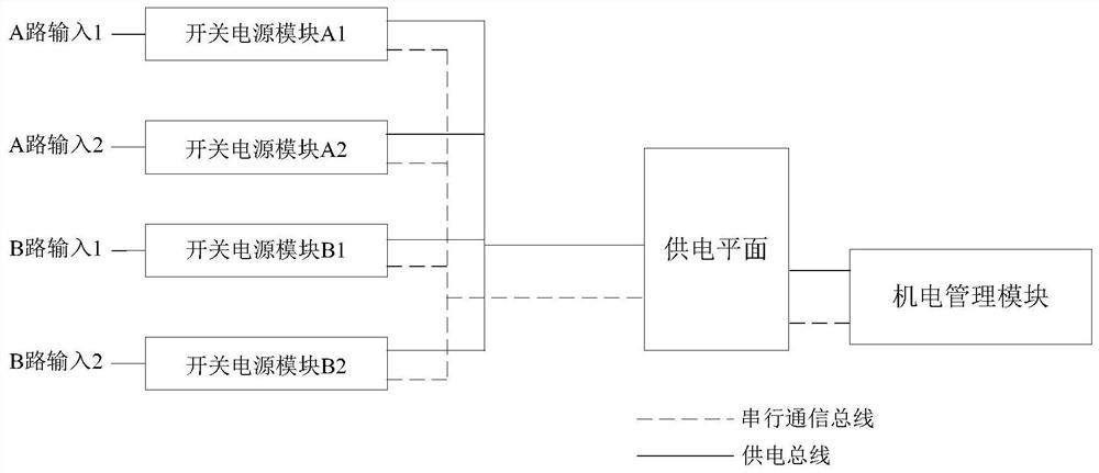
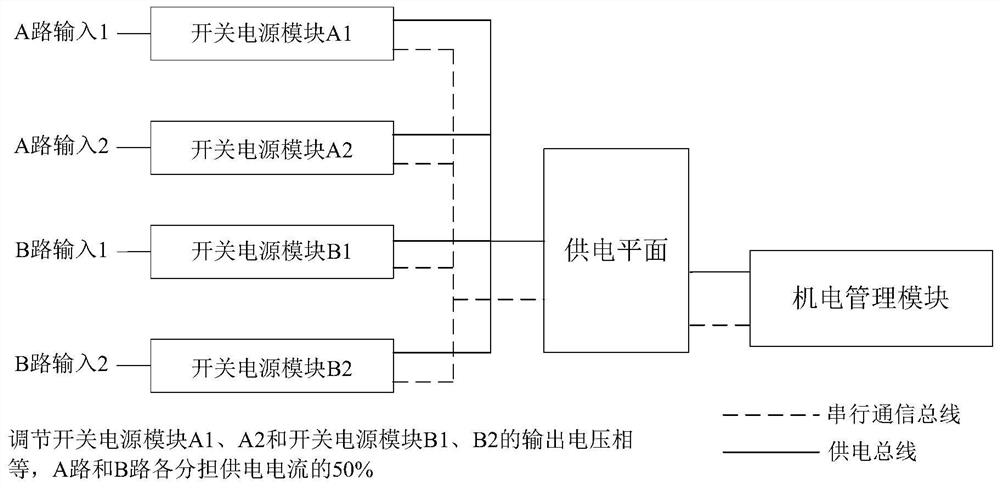
[0085] Such as figure 2 As shown in FIG. 2 , it is a schematic diagram of application of proportional distribution of a power supply system for communication equipment provided by an embodiment of the present invention. The power supply system adopts 2+2 redundant power supply, that is, the power supply terminals provided by the power distribution cabinet are 2+2 lines, and the number of switching power supply modules in the power supply system is 2+2.
[0086] The communication equipment in the power supply system is powered by the only power supply plane. Through the output voltage adjustment technology of the switching power supply module, the output voltage of the switching power supply module in the power supply system is adjusted to provide different current carrying values of the main / standby power supply of the power distribution cabinet. So as to meet the requirements of AC direct supply in the IDC computer room or the power supply requirements of power supply cutt...
PUM
 Abstract
Description
Claims
Application Information
 - R&D
- Intellectual Property
- Life Sciences
- Materials
- Tech Scout
- Unparalleled Data Quality
- Higher Quality Content
- 60% Fewer Hallucinations
Browse by: Latest US Patents, China's latest patents, Technical Efficacy Thesaurus, Application Domain, Technology Topic, Popular Technical Reports.
© 2025 PatSnap. All rights reserved.Legal|Privacy policy|Modern Slavery Act Transparency Statement|Sitemap|About US| Contact US: help@patsnap.com


