Constant-current output control system

A control system and constant current output technology, applied in the electronic field, can solve problems such as complex circuits, high cost, and low efficiency of BUCK circuits

Pending Publication Date: 2020-07-14
深圳市蓝色起源发展有限公司
View PDF0 Cites 0 Cited by
  • Summary
  • Abstract
  • Description
  • Claims
  • Application Information

AI Technical Summary

Problems solved by technology

[0005] Aiming at the above-mentioned shortcomings existing in the prior art, the present invention provides a constant current output control system, which can effectively solve the problems

Method used


Image

  • Constant-current output control system
  • Constant-current output control system

Examples


Embodiment

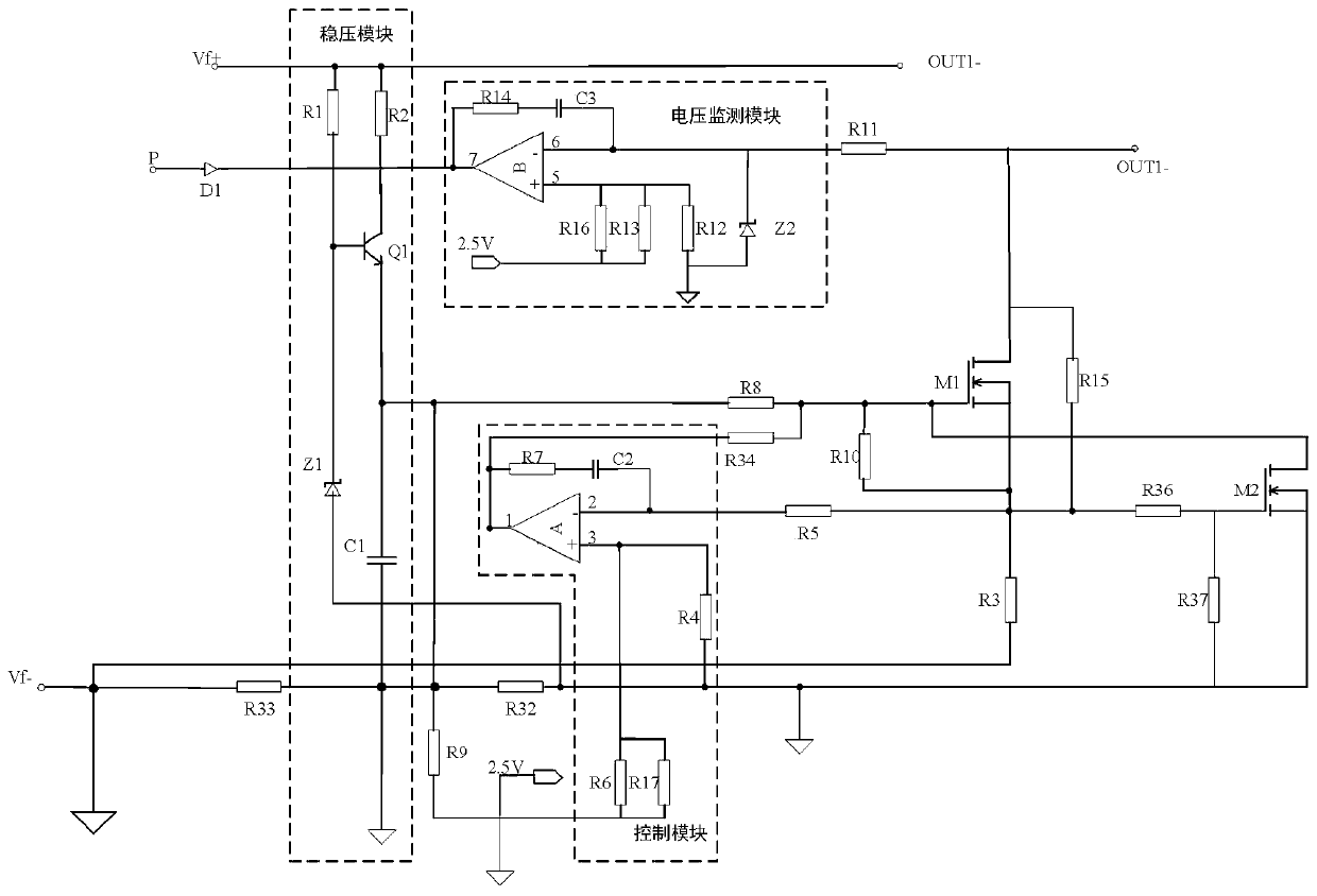
[0026] like figure 2As shown, a constant current output control system includes: a first power supply Vf, a voltage stabilizing module, a resistor R8, a transistor M1, a resistor R3, a resistor R5, a control module, a resistor R34, a resistor R11, a voltage monitoring module, and a diode D1, The positive pole Vf+ of the power supply is connected to the input terminal of the voltage stabilizing module, the output terminal of the voltage stabilizing module is connected to the gate G of the transistor M1 through the resistor R8, the source S of the transistor M1 is connected to the negative pole Vf- of the power supply through the resistor R3, and the transistor M1’s The source S is connected to the input terminal of the control module through the resistor R5, the output terminal of the control module is connected to the gate G of the transistor M1 through the resistor R34, and the drain D of the transistor M1 is connected to the input terminal of the voltage monitoring module th...


PUM


Abstract

The invention discloses a constant-current output control system, and relates to the technical field of electronics. The anode of a power supply is connected with the input end of a voltage-stabilizing module; the output end of the voltage-stabilizing module is connected with the grid electrode of a transistor M1 through an eighth resistor R8; the source electrode of the transistor M1 is connectedwith the negative electrode of a first power supply through a third resistor R3; the source electrode of the transistor M1 is connected with the input end of a control module through a fifth resistorR5; the output end of the control module is connected with the grid electrode of the transistor M1 through a thirty-fourth resistor R34; the drain electrode of the transistor M1 is connected with theinput end of a voltage monitoring module through an eleventh resistor R11, the output end of the voltage monitoring module is connected with an optical coupling element through a first diode D1, thepositive electrode of the first power supply is connected with the positive electrode of s load, and the connection point of the eleventh resistor R11 and the transistor M1 is connected with the negative electrode of the load. The system has the advantages of being simple in structure, low in cost, high in efficiency and free of EMI interference.

Description

technical field [0001] The invention relates to the field of electronic technology, in particular to a constant current output control system. Background technique [0002] LED lighting technology is developing rapidly due to its high efficiency, energy saving, and longevity. However, due to its semiconductor characteristics, it has brought requirements for its driving power supply: First, the power problem. To increase the luminous flux, it is necessary to inject enough power into the LED chip. , but the temperature rise of the LED cannot be too high, otherwise it will affect the life and light efficiency, and because it is a diode itself, it has negative temperature characteristics, it is not enough to provide its stable voltage, and constant current control must be given; secondly, LED lighting needs Multiple LED tubes are connected in series or in parallel. Its discrete parameters are an important problem, and it is impossible for manufacturers to be consistent, so this...

Claims


Application Information

Patent Timeline
IPC IPC(8): H05B45/345
Inventor 崔华徐月玲
Owner 深圳市蓝色起源发展有限公司
Why Eureka
Try Eureka