Valve

A solenoid and protective sleeve technology, applied in the field of valves, can solve problems such as errors, and achieve the effects of low cost, simple manufacturing, and reliable protection

Inactive Publication Date: 2020-07-14
CPT GRP GMBH
View PDF9 Cites 0 Cited by
  • Summary
  • Abstract
  • Description
  • Claims
  • Application Information

AI Technical Summary

Problems solved by technology

This in turn causes an error message in the controller that operates the solenoid

Method used


Image

  • Valve
  • Valve
  • Valve

Examples


Embodiment Construction

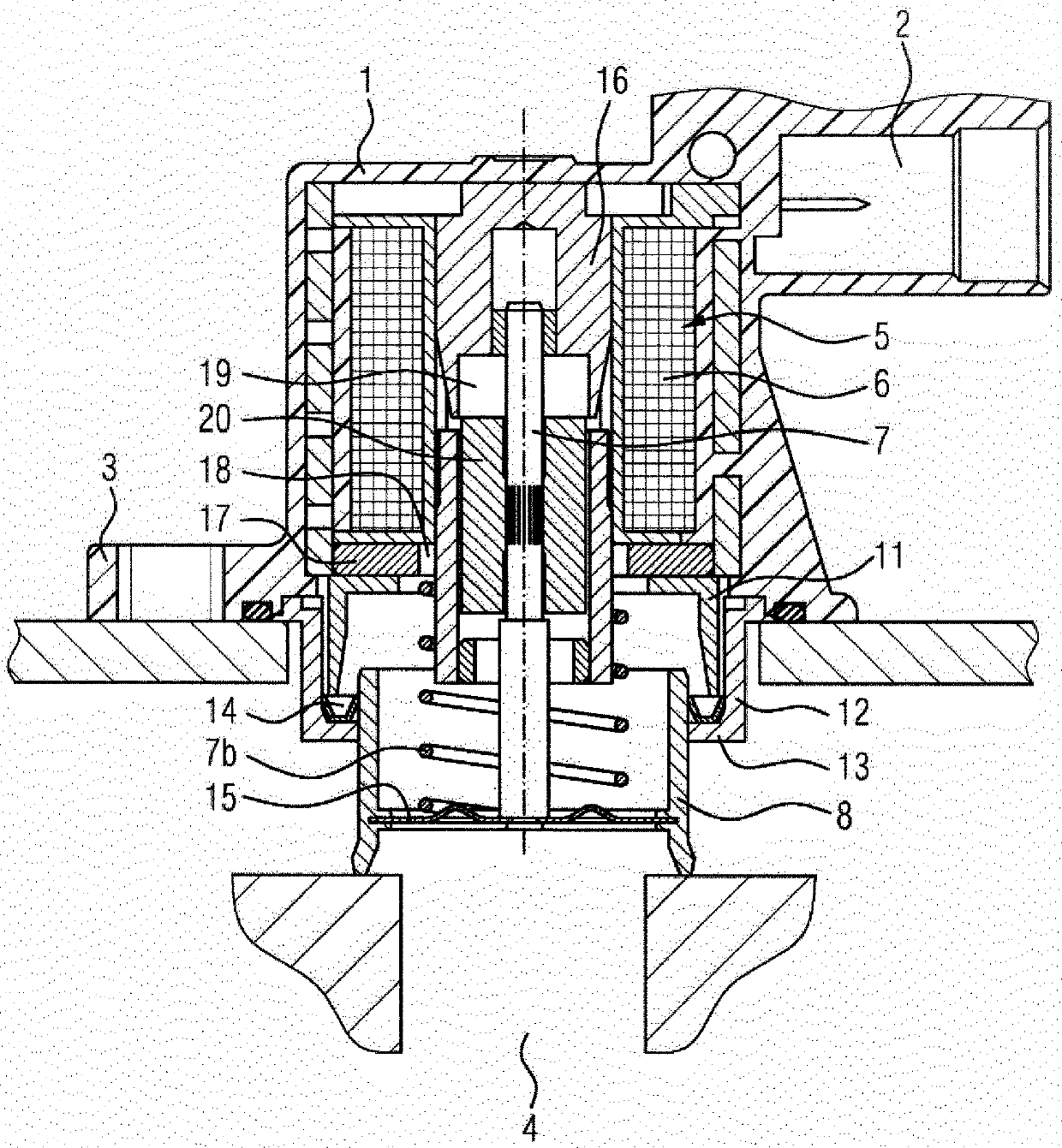
[0015] figure 1 The valve is shown, including the housing 1 . Furthermore, the housing 1 has an integrally formed flange 3 , via which the housing 1 is flanged to a turbocharger (not shown) in the region of the bypass line. The electrical contacting of the solenoid 5 , which is arranged in the housing 1 , takes place via the socket 2 . The solenoid 5 has a coil 6 which acts on a metal rod 7 . The metal rod 7 is connected to a pot-shaped piston 8 , which has a sealing surface 10 on the circumference of its lower part 9 , which cooperates with a valve seat (not shown). Here, the spring 7a pushes the piston 8 towards the valve seat. The housing 1 also has a cylindrical section 11 which extends in the direction of the piston 8 . A cylindrical bushing 12 connected to the housing surrounds the cylindrical section 11 . The cylindrical bush 12 has a radially inward flange 13 on which a seal 14 is placed. The seal 14 here seals the piston 8 relative to the housing 1 . The openin...


PUM


Abstract

The invention relates to a valve comprising a housing and a solenoid which is arranged in the housing. The solenoid comprises a coil, an armature, an upper stator, and a lower stator, and the statorsare designed such that the armature moves axially between the stators under the effect of a magnetic force. The valve also comprises a pin which is rigidly connected to the armature, a cup-shaped piston which is connected to the pin, a spring which moves the piston away from the solenoid in the event of a loss of the magnetic force, and a socket which is arranged on the housing in order to supplythe solenoid with electric energy. The solenoid (5) is equipped with a protective sleeve (21) which separates the region of the piston (8) from the region of the socket such that no medium from the region of the piston (8) can reach the region of the socket.

Description

technical field [0001] The invention relates to a valve comprising a housing and a solenoid arranged in the housing, wherein the solenoid comprises a coil, an armature, an upper stator and a lower stator, the stators are designed such that when a magnetic force acts between the stators When the armature moves axially, the valve also includes a rod fixedly connected to the armature, a pot-shaped piston connected to the rod, a spring that moves the piston away from the solenoid when the magnetic force disappears, and is arranged on the housing so as to provide Socket for supplying electrical power to the solenoid. Background technique [0002] Such valves are used primarily as air steering valves on turbochargers in motor vehicles in order to open a bypass to the intake side during freewheeling and are therefore known. In order to prevent excessive braking of the turbocharger, but also to ensure a fast start-up, fast opening and closing of the valve is an important prerequisi...

Claims


Application Information

Patent Timeline
Patent Type & Authority Applications(China)
IPC IPC(8): F16K27/02F02B37/18F16K31/06
CPCF16K27/029F16K31/0655F16K31/0675Y02T10/12F02B37/16
Inventor R·博南诺
Owner CPT GRP GMBH
Why Eureka
Try Eureka