

Garden irrigation device convenient for saving water
An equipment and garden technology, applied in the field of garden irrigation equipment, can solve the problems of insufficient irrigation, poor fertilization effect, unfavorable plant growth, etc., and achieve the effect of increasing the irrigation surface, improving the stirring effect, and improving the irrigation effect.
- Summary
- Abstract
- Description
- Claims
- Application Information
AI Technical Summary
Problems solved by technology
Method used
Image

Examples
Embodiment 1
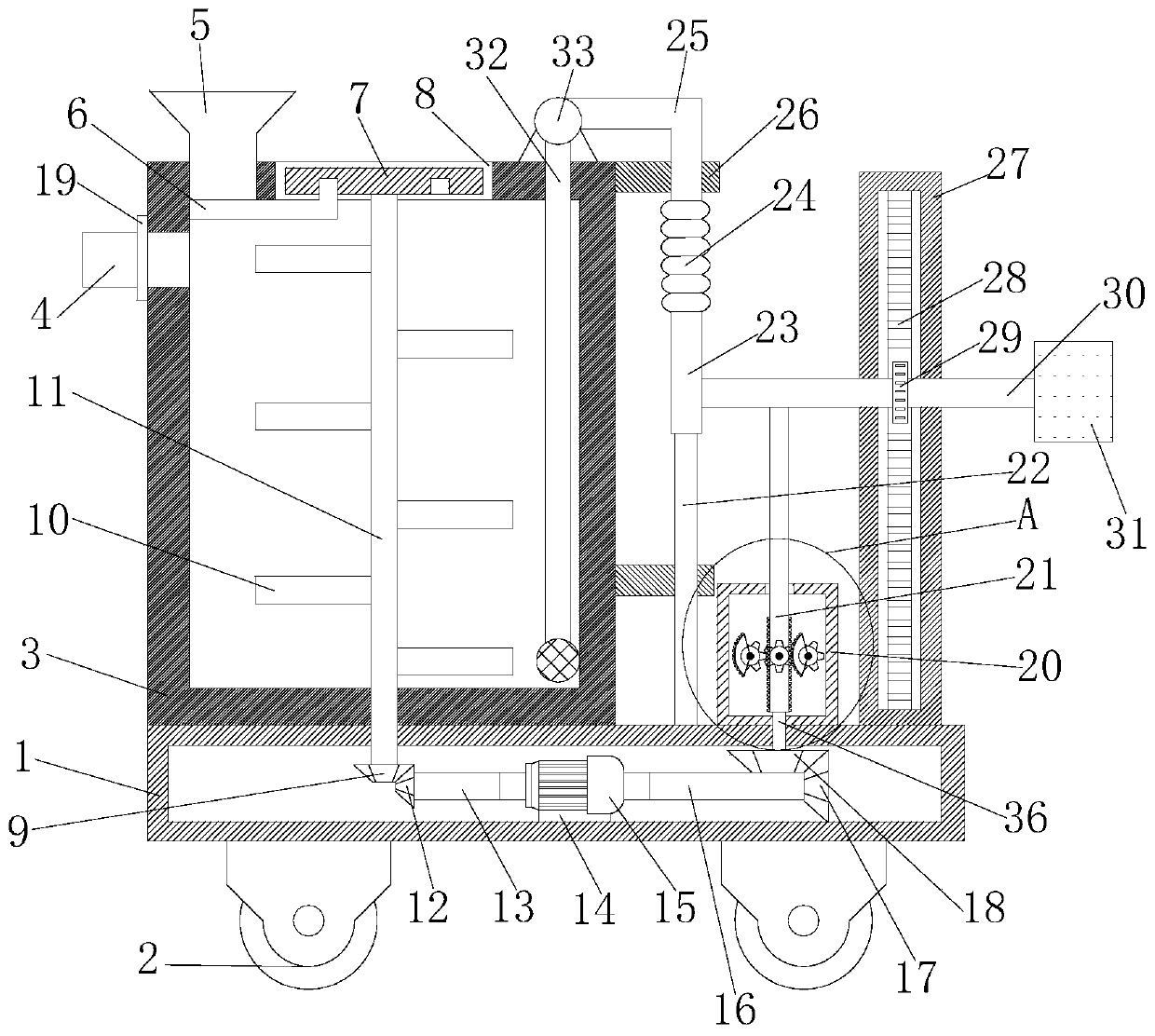
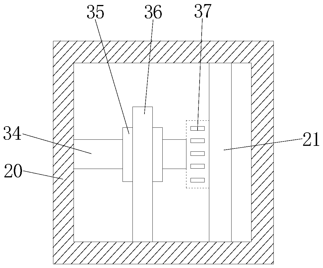
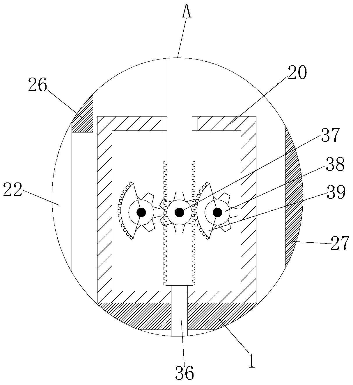
[0028] refer to Figure 1-5 , a kind of garden irrigation equipment convenient for water saving, comprising a base 1, the top of the base 1 is fixedly installed with a water tank 3, a regulating box 20 and a regulating box 27 by welding, the base 1 is a hollow structure, and the inner wall of the bottom of the base 1 is fixedly installed by welding There is a motor base 14, on the motor base 14, a double-axis motor 15 is fixedly installed by bolts, and on the two output shafts of the double-axis motor 15, one end of the first rotating shaft 13 and one end of the second rotating shaft 16 are fixedly installed respectively, The other end of two rotating shafts 16 is fixedly installed with first bevel gear 17, and second bevel gear 18 is meshed on the first bevel gear 17, and one end of screw rod 36 is fixedly installed on the second bevel gear 18, and screw rod 36 The other end extends into the adjustment box 20 and is fixedly installed and engaged with a turbine 35. One end of ...
Embodiment 2
[0040] refer to Figure 1-5 , a kind of garden irrigation equipment convenient for water saving, comprising a base 1, the top of the base 1 is fixedly installed with a water tank 3, a regulating box 20 and a regulating box 27 by welding, the base 1 is a hollow structure, and the inner wall of the bottom of the base 1 is fixedly installed by welding There is a motor base 14, on the motor base 14, a double-axis motor 15 is fixedly installed by bolts, and on the two output shafts of the double-axis motor 15, one end of the first rotating shaft 13 and one end of the second rotating shaft 16 are fixedly installed respectively, The other end of two rotating shafts 16 is fixedly installed with first bevel gear 17, and second bevel gear 18 is meshed on the first bevel gear 17, and one end of screw rod 36 is fixedly installed on the second bevel gear 18, and screw rod 36 The other end extends into the adjustment box 20 and is fixedly installed and engaged with a turbine 35. One end of ...
PUM
 Abstract
Description
Claims
Application Information