Instrument and meter surface dust removal device

A technology for dust removal devices and instruments, which is applied in the direction of removing smoke and dust, chemical instruments and methods, cleaning methods and utensils, etc., can solve the problems of slow dust removal, long time consumption, low work efficiency, etc. The effect of polluted air and high work efficiency

Inactive Publication Date: 2020-07-17
南京奥亚美电子科技有限公司
View PDF6 Cites 5 Cited by
  • Summary
  • Abstract
  • Description
  • Claims
  • Application Information

AI Technical Summary

Problems solved by technology

[0003] When the instrument is placed for a long time, a lot of dust will accumulate on the surface, so it needs to be dedusted. At present, it is manually dedusted. Manual dedusting is not only slow in dust removal speed, but also low in work efficiency. It takes a lot of time. And the dust removal effect is general, therefore, in view of the above status quo, there is an urgent need to develop a surface dust removal device for instruments and meters to overcome the deficiencies in current practical applications.

Method used


Image

  • Instrument and meter surface dust removal device
  • Instrument and meter surface dust removal device
  • Instrument and meter surface dust removal device

Examples


Embodiment 1

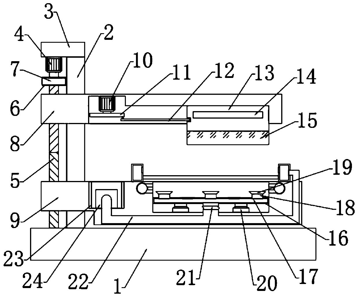
[0025] see Figure 1-3 In the embodiment of the present invention, a surface dust removal device for instruments and meters includes a bottom plate 1, a plurality of support rods 2 are fixedly connected at the top of the bottom plate 1, and a top plate 3 is fixedly connected at the top of the support rod 2. A movable plate 8 is provided on the outside of the rod 2 in a sliding connection, and a support plate 9 slidably connected with the support rod 2 is provided on the lower side of the movable plate 8. A cleaning mechanism is provided inside the movable plate 8 , and both the movable plate 8 and the support plate 9 are connected to an adjustment mechanism arranged at the bottom of the top plate 3 .

Embodiment 2

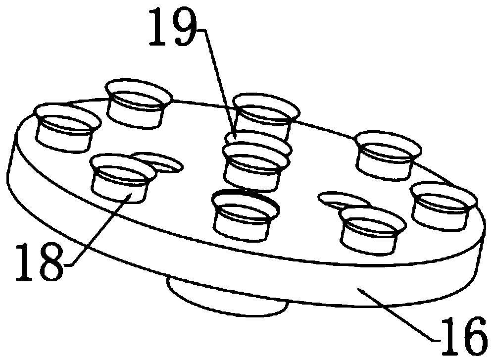
[0027] In this embodiment, the fixing mechanism includes a placement slot provided at the top of the support plate 9 , a placement plate 16 is slidably connected to the inner side of the placement slot, and the bottom end of the placement plate 16 and the support plate 9 are fixedly connected with a placement plate 16 . For the telescopic rod 20, a cavity 17 is provided on the inner side of the placing plate 16, the top of the cavity 17 is provided with a number of dust suction ports and a first connecting pipe 18, and the top of the first connecting pipe 18 is fixedly connected with a suction cup 19. , the bottom of the cavity 17 is fixedly connected with a conduit, and the other end of the conduit is connected to the dust suction mechanism through a hose 21 .

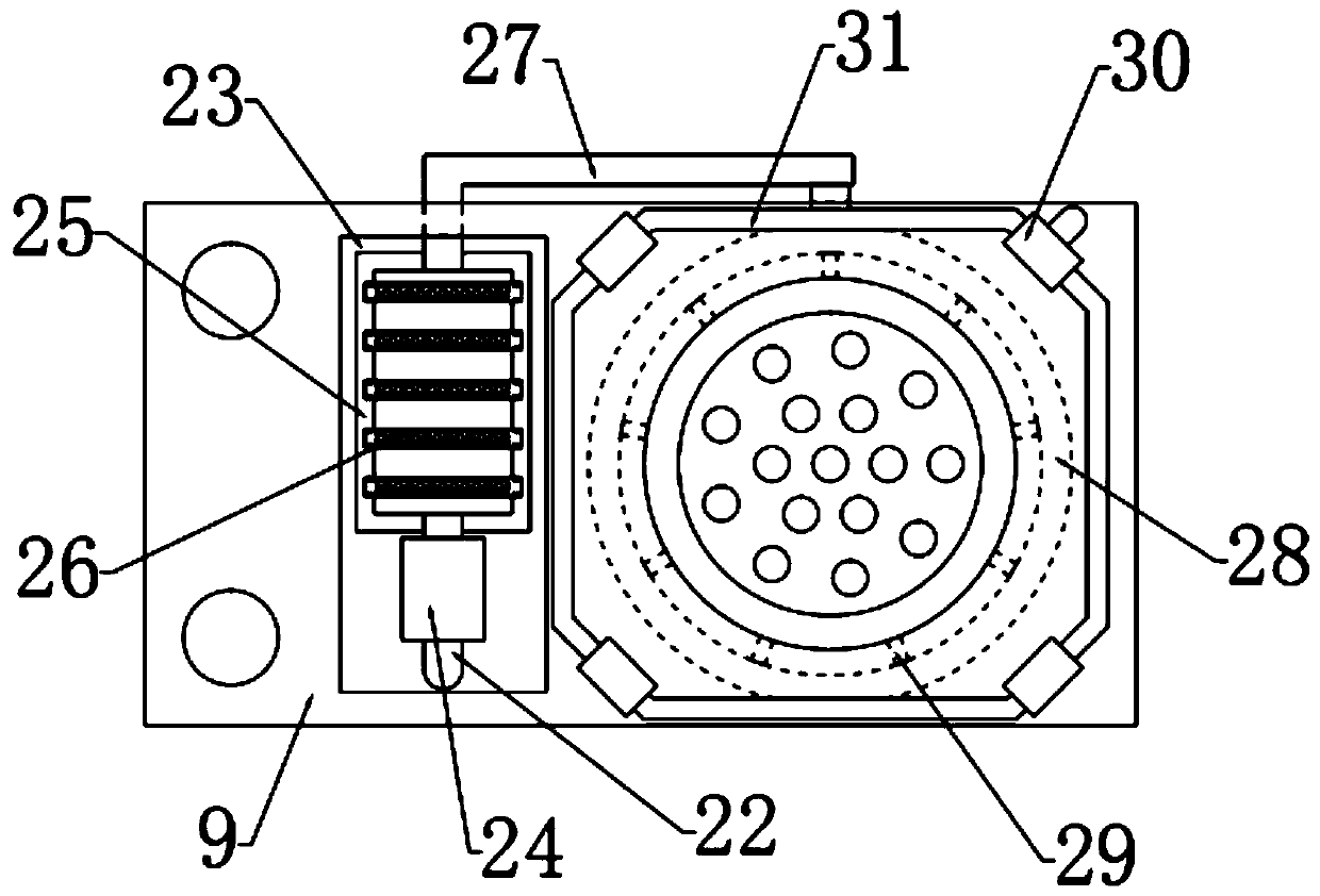
[0028] In this embodiment, the dust suction mechanism includes a groove 23 provided on the top of the support plate 9 , an air pump 24 is bolted on the inner side of the groove 23 , and the input end of the air pump 24...


PUM


Abstract

The invention relates to the field of instrument and meter dust removal devices, in particular to an instrument and meter surface dust removal device which comprises a bottom plate. A plurality of supporting rods are arranged at the top of the bottom plate, a top plate is arranged at the tops of the supporting rods, a movable plate is slidably connected to the outer sides of the supporting rods, asupporting plate is arranged on the lower side of the movable plate, a fixing mechanism arranged on the inner side of the supporting plate, a dust collection mechanism is arranged on the outer side of the fixing mechanism, and a cleaning mechanism is arranged on the inner side of the movable plate. According to the instrument and meter surface dust removal device, the dust removing mechanism is arranged, dust is blown away from the surface of an instrument and meter through a scouring mechanism, the blown-off dust is absorbed by a dust absorbing block, and the dust is absorbed by a dust absorbing opening formed in the top end of a placing disc, the dust generated in the sweeping and scouring process can be effectively collected, and air pollution caused by the dust is avoided; and the cleaning mechanism is arranged, a brush is made to conduct dust removal on the surface of the instrument and meter through left-right reciprocating motion of the movable block, the dust removal speed ishigh, and the working efficiency is high.

Description

technical field [0001] The invention relates to the field of dust removal devices for instruments, in particular to a surface dust removal device for instruments. Background technique [0002] Instrumentation is an instrument or equipment used to detect, measure, observe, and calculate various physical quantities, material components, physical parameters, etc. Vacuum leak detectors, pressure gauges, length measuring instruments, microscopes, multipliers, etc. are all instruments. In a broad sense, instruments and meters can also have functions such as automatic control, alarm, signal transmission and data processing, such as pneumatic adjustment instruments used in automatic control of industrial production processes, electric adjustment instruments, and distributed instrument control systems. Instrumentation. [0003] When the instrument is placed for a long time, there will be a lot of dust on the surface, so it needs to be dedusted. At present, it is manually dedusted. ...

Claims


Application Information

Patent Timeline
Patent Type & Authority Applications(China)
IPC IPC(8): B08B5/02B08B5/04B08B15/04B08B1/00
CPCB08B1/002B08B1/008B08B5/02B08B5/04B08B15/04
Inventor 刘洁珍
Owner 南京奥亚美电子科技有限公司
Why Eureka
Try Eureka