
A stamping composite die and stamping machine

A composite mold and machine base technology, applied in the field of stamping equipment, can solve the problems of high cost of mold opening, long equipment debugging time period, low efficiency of switching and processing of blanking products, etc., and achieve the effect of reducing processing cost input.

Active Publication Date: 2022-02-15
重庆庆铃模具有限公司
View PDF10 Cites 0 Cited by
  • Summary
  • Abstract
  • Description
  • Claims
  • Application Information

AI Technical Summary

Problems solved by technology

[0005] In order to make up for the deficiencies of the existing technology and solve the problems in the prior art, the blanking molds of the stamping composite mold are all special molds, and different molds need to be replaced for different blanking products. On the one hand, different molds need to be processed, and the cost of mold opening is relatively high. , and the product equipment investment cost is high; on the other hand, for different blanking products, manual replacement of molds is required for flanging and pressing, which requires high labor costs. At the same time, the equipment debugging period is long, which affects the efficiency of switching processing of blanking products Lower problems, the present invention proposes a stamping composite die and stamping machine

Method used


Image

  • A stamping composite die and stamping machine
  • A stamping composite die and stamping machine
  • A stamping composite die and stamping machine

Examples


Embodiment Construction

[0023] In order to make the technical means, creative features, goals and effects achieved by the present invention easy to understand, the present invention will be further described below in conjunction with specific embodiments.

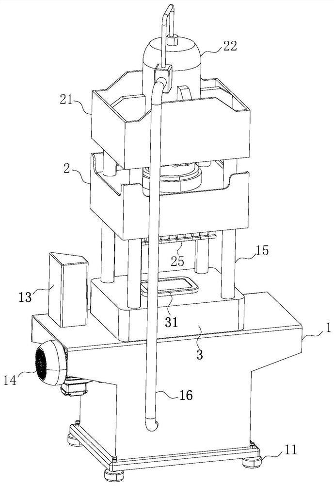
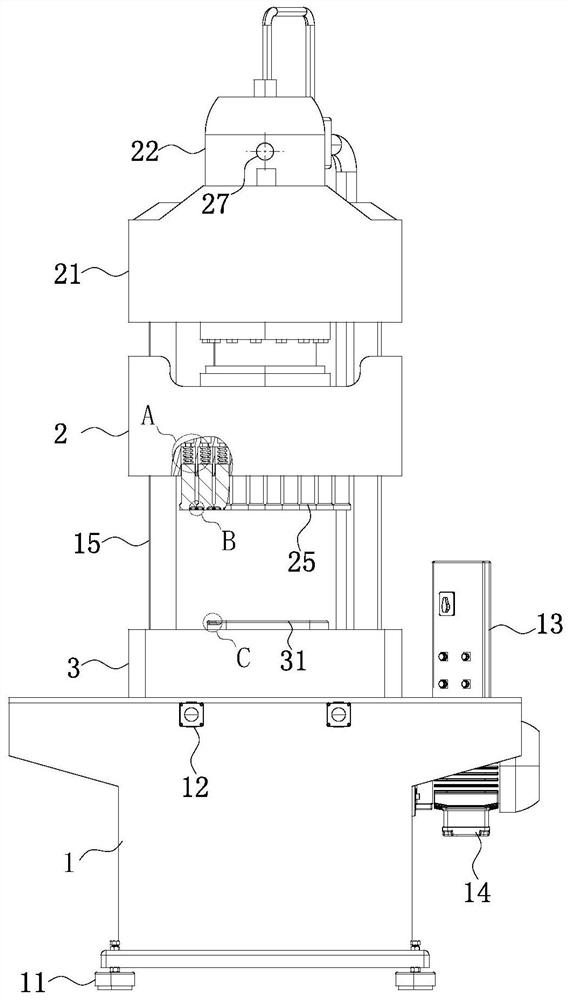
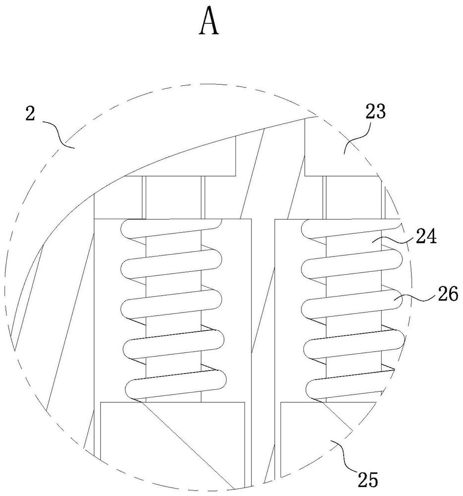
[0024] Such as Figure 1 to Figure 5As shown, a kind of stamping composite die described in the present invention comprises a base 1, an upper die 2 and a lower die 3; the cross section of the base 1 is a cubic structure design of a "T" shape; the base 1 The lower surface of the lower surface of the base 1 is fixedly connected to the four corners of the base 1 with adjustment supports 11; the upper surface of the base 1 is fixedly connected with the lower mold 3 at the middle position of the base 1; The upper surface is provided with a limited cavity; the inside of the limited cavity is fixedly connected with a blank holder product 31; the front end of the base 1 is provided with two control buttons 12 near the upper surface of the base 1; The up...


PUM


Abstract

The invention belongs to the technical field of stamping equipment, specifically a stamping compound die and a stamping machine, including a machine base, an upper mold and a lower mold; the upper surface of the machine base is fixedly connected with a lower mold at the middle position of the machine base; The upper surface of the lower mold is fixedly connected with support columns near the four corners; the upper surfaces of the four support columns are jointly fixed with the same fixed top plate; Mounting hole; the interior of the mounting hole is fixedly connected with a pressure cylinder, and the piston rod of the pressure cylinder passes through the mounting hole and extends to the lower position of the fixed top plate; the lower end surface of the piston rod of the pressure cylinder is fixedly connected with an upper mold; The lower surface of the upper die is provided with uniformly arranged pressure columns directly above the blank holder products; through the present invention, the versatility of the stamping composite mold is effectively realized, the processing cost of the blank holder products of the enterprise is reduced, and the profit is realized. maximize.

Description

technical field [0001] The invention belongs to the technical field of stamping equipment, in particular to a stamping compound die and a stamping machine. Background technique [0002] The principle of the stamping machine is to drive the flywheel through the motor, and through the clutch, the transmission gear drives the crank linkage mechanism to move the slider up and down, and drives the drawing die to form the steel plate. The so-called double action means that the press has two sliders, which are divided into an inner slider and an outer slider. The inner slider drives the punch or die of the mold, and the outer slider drives the blankholder on the mold. When the blank holder first moves to press the edge of the steel plate, the inner slider moves to stretch. In fact, what we call a punching machine is a common name, which is what we often call a punching machine. The scientific name should be called the press. [0003] In the prior art, the blanking dies of the sta...

Claims


Application Information

Patent Timeline
Patent Type & Authority Patents(China)
IPC IPC(8): B21D37/12B21D22/22B21D55/00
CPCB21D37/12B21D22/22B21D55/00
Inventor 李学海李志城王志伟
Owner 重庆庆铃模具有限公司
Learn More