Self-guided multi-degree-of-freedom wave energy power generation device

A power generation device and self-guided technology, which is applied in the direction of ocean energy power generation, engine components, machines/engines, etc., can solve the problem that the mechanical principle can only capture the vertical energy or longitudinal energy of waves, and the power generation efficiency cannot meet the ideal requirements. Effective and full use of waves and other problems to achieve the effect of improving capture ability, improving dynamic stability and reducing blocking effect

Inactive Publication Date: 2020-07-17
JIANGSU UNIV OF SCI & TECH
View PDF6 Cites 5 Cited by
  • Summary
  • Abstract
  • Description
  • Claims
  • Application Information

AI Technical Summary

Problems solved by technology

Its energy conversion devices are mainly linear motors and hydraulic systems, but the power generation efficiency cannot meet the ideal requirements, and the energy utilization rate is low
[0004] Therefore, for the utilization of wave energy in the existing wave energy generating device, only the vertical energy or longitudinal energy of the wave is captured solely through some mechanical principles, and the energy of the wave cannot be effectively and fully utilized.
Moreover, most devices can only realize the utilization of wave energy in a single direction, and cannot realize the utilization of wave energy in all directions according to the characteristics of wave direction uncertainty.

Method used


Image

  • Self-guided multi-degree-of-freedom wave energy power generation device
  • Self-guided multi-degree-of-freedom wave energy power generation device
  • Self-guided multi-degree-of-freedom wave energy power generation device

Examples


Embodiment Construction

[0034] The technical solutions of the present invention will be further described below in conjunction with the accompanying drawings and embodiments.

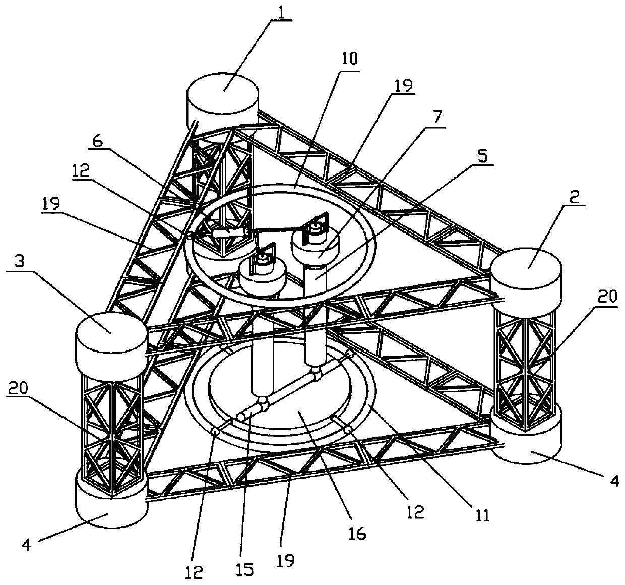
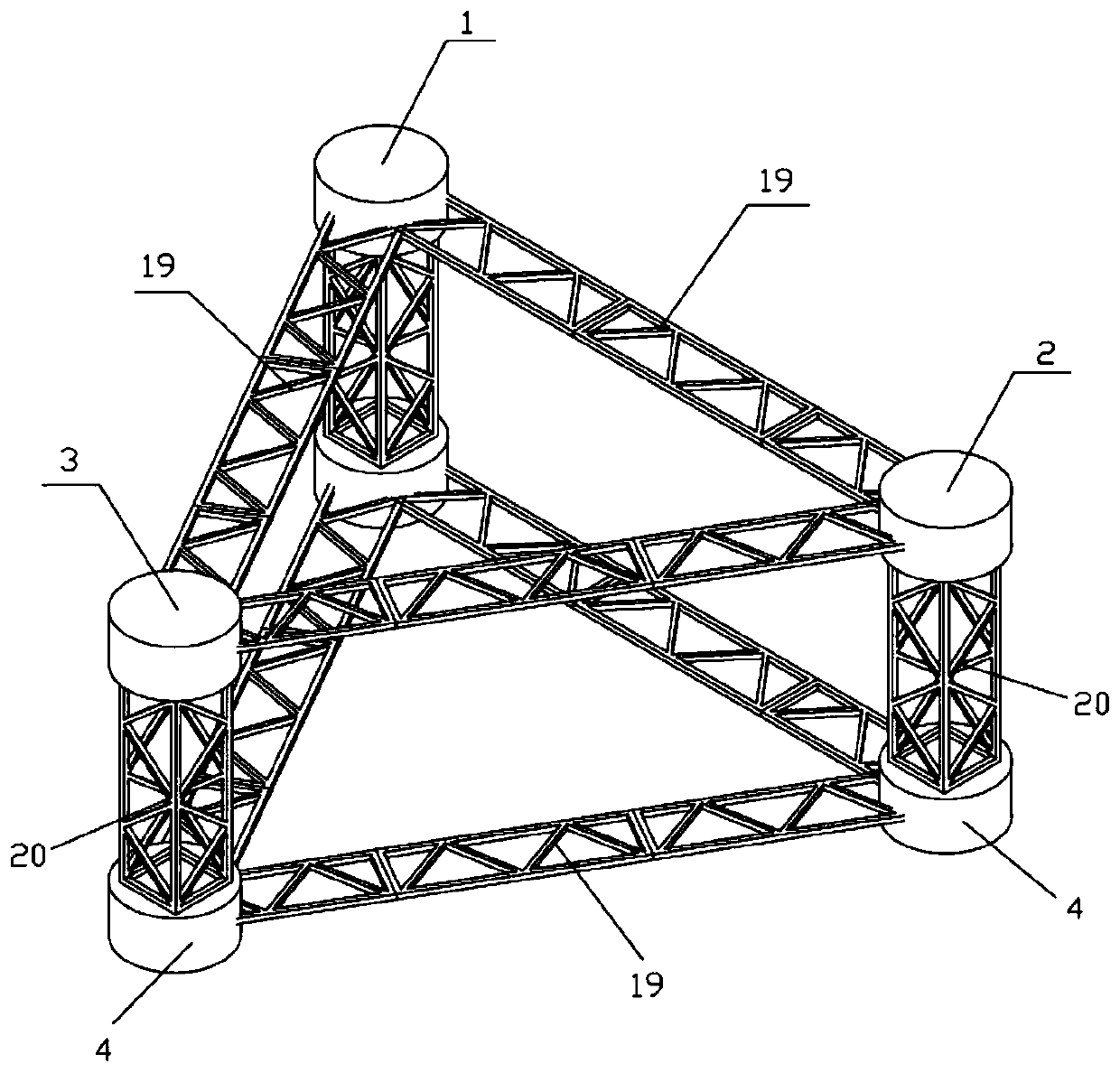
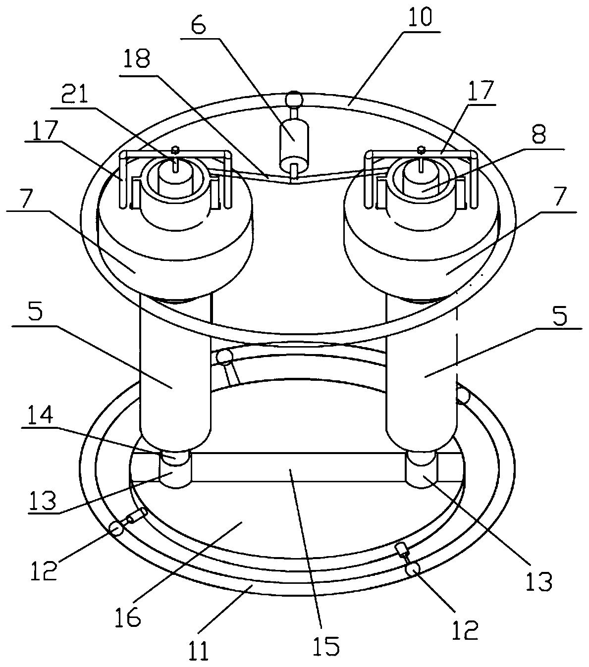
[0035] like figure 1 As shown, a self-guided multi-degree-of-freedom wave power generation device in this embodiment includes a support module and a power generation module disposed inside the support module. The support module is composed of an upper cylindrical buoyant tank structure (including the first buoyant tank 1, the second buoyant tank 2 and the third buoyant tank 3) and the lower corresponding cylindrical ballast tank 4 structure. The power generation module includes a self-guided hydraulic PTO device and a magnetic induction power generation device. Under the action of waves in different directions, the self-guided hydraulic PTO device drives the two columns 5 to pitch in different directions, making the columns 5 swing back and forth along the moving guide rail, so that the hydraulic power generation Generator 6 ...


PUM


Abstract

The invention discloses a self-guided multi-degree-of-freedom wave energy power generation device. The self-guided multi-degree-of-freedom wave energy power generation device comprises a support module and a power generation module; the support module is of a multi-box truss structure; the power generation module comprises a self-guided hydraulic PTO device and a magnetic induction power generation device; in the self-guided hydraulic PTO power generation device, two stand columns are driven by waves to pitch in different directions, and the stand columns swing back and forth to make a hydraulic generator generate power; and in the magnetic induction power generation device, double floats heave along the peripheries of the stand columns under the action of waves and drive magnetic rods toreciprocate up and down in the stand columns, and magnetic induction lines generated by the displacement of an electromagnetic field are cut by electromagnetic coils to generate electric energy. According to the self-guided multi-degree-of-freedom wave energy power generation device, a self-guided multi-degree-of-freedom wave energy capture system based on the combined motion of pitching and heaving is established, the defect that a traditional device only captures wave energy in one direction is overcome, the comprehensive utilization of wave energy in any direction is realized, and the waveenergy capture efficiency is greatly improved; and the self-guided multi-degree-of-freedom wave energy power generation device can be widely applied to existing marine engineering structures.

Description

technical field [0001] The invention belongs to the technical field of marine engineering, and in particular relates to a self-guiding multi-degree-of-freedom wave energy generating device. Background technique [0002] With the continuous rapid development of the world economy, the demand for energy is increasing. According to the current statistics of the average annual mining volume, China's oil resources will be exhausted by 2040, and natural gas will be exhausted by 2060. By 2300 The annual coal storage capacity will be fully mined. In addition, when fossil energy fuels are burned, harmful substances such as carbon monoxide, carbon dioxide, and inhalable particulate matter will be produced, which seriously pollutes the living environment of human beings and threatens the safety of human life. Therefore, in recent decades, how to effectively and fully utilize various renewable energy sources, including wave energy, water energy, wind energy, and solar energy, has attrac...

Claims


Application Information

Patent Timeline
Patent Type & Authority Applications(China)
IPC IPC(8): F03B13/20B63B35/44
CPCB63B35/44B63B2035/4466F03B13/182F03B13/1845F03B13/20Y02E10/30
Inventor 张万超陈东傅磊唐练洋徐天宇徐张
Owner JIANGSU UNIV OF SCI & TECH
Why Eureka
Try Eureka