Hydraulic cylinder

A technology of hydraulic cylinders and cylinder blocks, applied in the field of hydraulic cylinders, can solve the problems of increased processing difficulty, poor buffering effect, uncontrollability, etc., and achieve the effects of reducing processing and matching accuracy requirements, facilitating processing and manufacturing, and improving motion resistance.

Active Publication Date: 2020-07-17
龙岩市山力工程液压有限公司
View PDF6 Cites 0 Cited by
  • Summary
  • Abstract
  • Description
  • Claims
  • Application Information

AI Technical Summary

Problems solved by technology

According to whether the area of ​​the orifice changes, it is divided into two buffer types: fixed throttling and variable throttling; at the beginning of buffering, the fixed throttling produces a large buffer braking force, but the buffer pressure decays quickly, and there is almost no buffering force in the later stage. What role does it play? The cushioning effect is very poor; the variable throttle buffer device changes the flow area with the change of the buffer stroke during the buffering process. When the conical surface is used, the pressure change in the initial stage of buffering is relatively gentle, but the pressure in the later stage changes greatly. When the parabola is used, a more ideal buffering effect can be achieved, but the processing requires CNC machine tools, the cost is high, and there is a sudden change in pressure at the beginning and end of buffering
[0004] In addition, in order to achieve a better buffering effect, the existing buffer device must ensure the concentricity of the buffer device and the cylinder or end cover, which requires ensuring the matching accuracy of the end cover and the piston rod, the cylinder and the end cover during the processing process. The matching accuracy of the cylinder and the piston, the matching accuracy of the piston and the piston rod, the matching accuracy of the buffer sleeve and the piston rod, and the matching accuracy of the buffer sleeve and the end cover increase the difficulty of processing on the one hand, and on the other hand Due to the uncontrollable accumulation of errors, the buffering effects of the two hydraulic cylinders with the same machining accuracy are inconsistent, and the buffering effect of the final hydraulic cylinder cannot be guaranteed.

Method used


Image

  • Hydraulic cylinder
  • Hydraulic cylinder
  • Hydraulic cylinder

Examples


Embodiment Construction

[0027] The technical solutions of the present invention will be further described in detail below in conjunction with the accompanying drawings and embodiments.

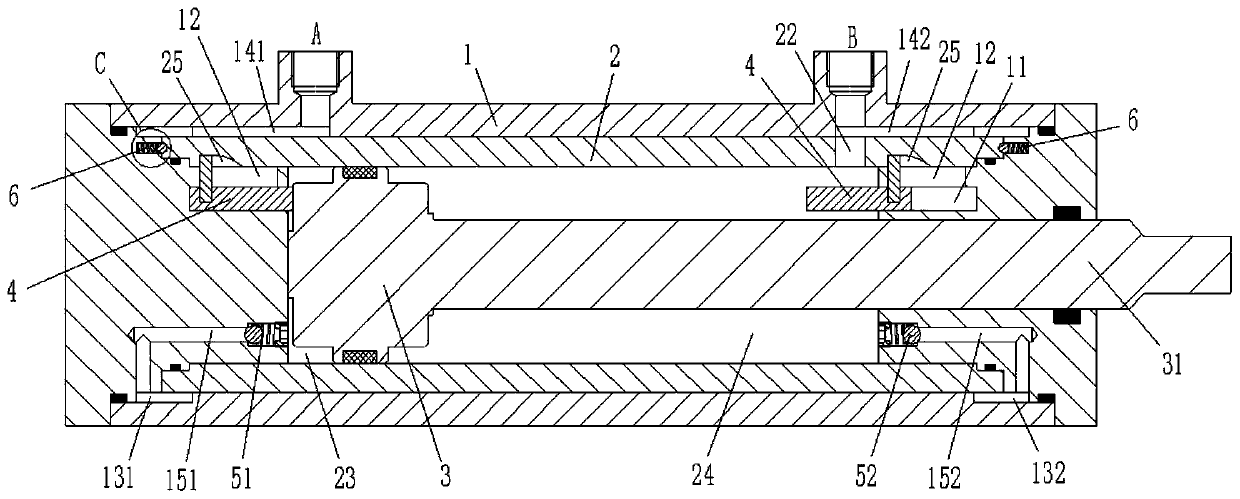
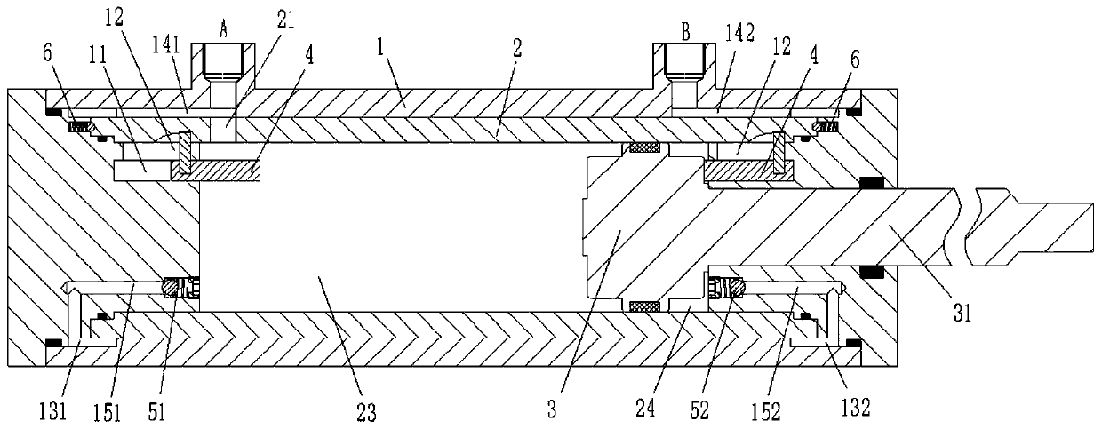
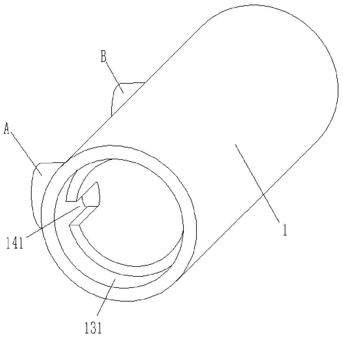
[0028] combine Figure 1 to Figure 5 As shown, the hydraulic cylinder of this embodiment includes a cylinder body 1 , a cylinder barrel 2 and a piston 3 . Wherein, the cylinder body 1 is provided with an A port and a B port, and the cylinder body 2 is provided with a first through hole 21 and a second through hole 22, and the cylinder body 2 can reciprocate relative to the cylinder body 1 inside the cylinder body 1 turn. The piston 3 is located inside the cylinder 2 and divides the inside of the cylinder 2 into a first control chamber 23 and a second control chamber 24 which are not connected to each other. A piston rod 31 is provided at one end of the piston 3 , and the piston rod 31 protrudes to the outside of the cylinder body 1 through the first control cavity 23 . The first control chamber 23 communicates wit...


PUM


Abstract

The invention relates to the field of hydraulic cylinders, and discloses a hydraulic cylinder having a buffering function. The hydraulic cylinder comprises a cylinder body, a cylinder barrel and a piston, wherein the cylinder body is provided with an A port and a B port, the cylinder barrel is provided with a first through hole and a second through hole, and the A port, B port, first through holeand second through hole are located inside the cylinder body and can make reciprocating motion relative to the cylinder body; the piston is located inside the cylinder barrel to divide the interior ofthe cylinder barrel into a first control cavity and a second control cavity; the first control cavity communicates the A port through the first through hole, the second control cavity communicates the B port through the second through hole, the piston makes reciprocating motion relative to the cylinder body under the pressure of a medium between the first control cavity and the second control cavity, and the cylinder barrel moves relative to the cylinder body when the piston moves to the terminal position of any one control cavity, so that the flow area between the through hole communicatingthe control cavity and the A port or B port is reduced, so as to reduce the discharge velocity of the medium in the control cavity. The hydraulic cylinder provided by the invention can not only realize the effective deceleration buffer of reciprocating motion process of the piston, but also is simple in structure and easy to process and manufacture.

Description

technical field [0001] The invention belongs to the technical field of hydraulic cylinders, in particular to a hydraulic cylinder with a buffer function. Background technique [0002] A hydraulic cylinder is a hydraulic actuator that converts hydraulic energy into mechanical energy and performs linear reciprocating motion (or swing motion). When the hydraulic cylinder is used to realize the reciprocating motion, not only the deceleration device can be eliminated, but also there is no transmission gap, and the motion is stable. It is widely used in various hydraulic systems. Among them, when the high-speed hydraulic cylinder moves to the end, it will produce a large impact. In order to reduce the impact, a hydraulic buffer device is usually added to the end of the hydraulic cylinder. [0003] There are many types of existing hydraulic cylinder buffer devices, but the essence is to add a section of mating surface before and after the piston, and divide the oil return chamber ...

Claims


Application Information

Patent Timeline
Patent Type & Authority Applications(China)
IPC IPC(8): F15B15/14F15B15/20F15B15/22
CPCF15B15/1423F15B15/1428F15B15/20F15B15/204F15B15/22F15B2211/755
Inventor 不公告发明人
Owner 龙岩市山力工程液压有限公司
Why Eureka
Try Eureka