Rock creep test method and device under action of multiple environments

A creep test and multi-environment technology, applied in the direction of applying stable tension/pressure to test the strength of materials, can solve the problems of less research on creep experiments, energy consumption, time consumption, etc., and achieve low instrument prices and high safety factors , The effect of simple operation of the test

Inactive Publication Date: 2020-07-17
DALIAN UNIV OF TECH
View PDF10 Cites 4 Cited by
  • Summary
  • Abstract
  • Description
  • Claims
  • Application Information

AI Technical Summary

Problems solved by technology

Due to the limited test time scale under the actual indoor test conditions, the use of general creep testing machines is time-consuming, energy-consuming and unstable.
Existing creep tests usually stop the test after holding the load for a certain period of time under a constant load, and it is impossible to carry out long-term rock creep tests under load.
With the rapid progress of rock engineering theory and practice, the research on rock creep has made great progress in theory, laboratory experiment and microcosmic aspect, but the experimental research on creep in complex environment is less. The indoor creep test of rock can not completely simulate the actual engineering environment, which leads to the inconsistency between the indoor test results and the actual engineering

Method used


Image

  • Rock creep test method and device under action of multiple environments
  • Rock creep test method and device under action of multiple environments
  • Rock creep test method and device under action of multiple environments

Examples


Embodiment 1

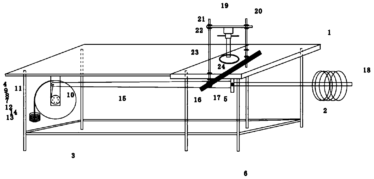
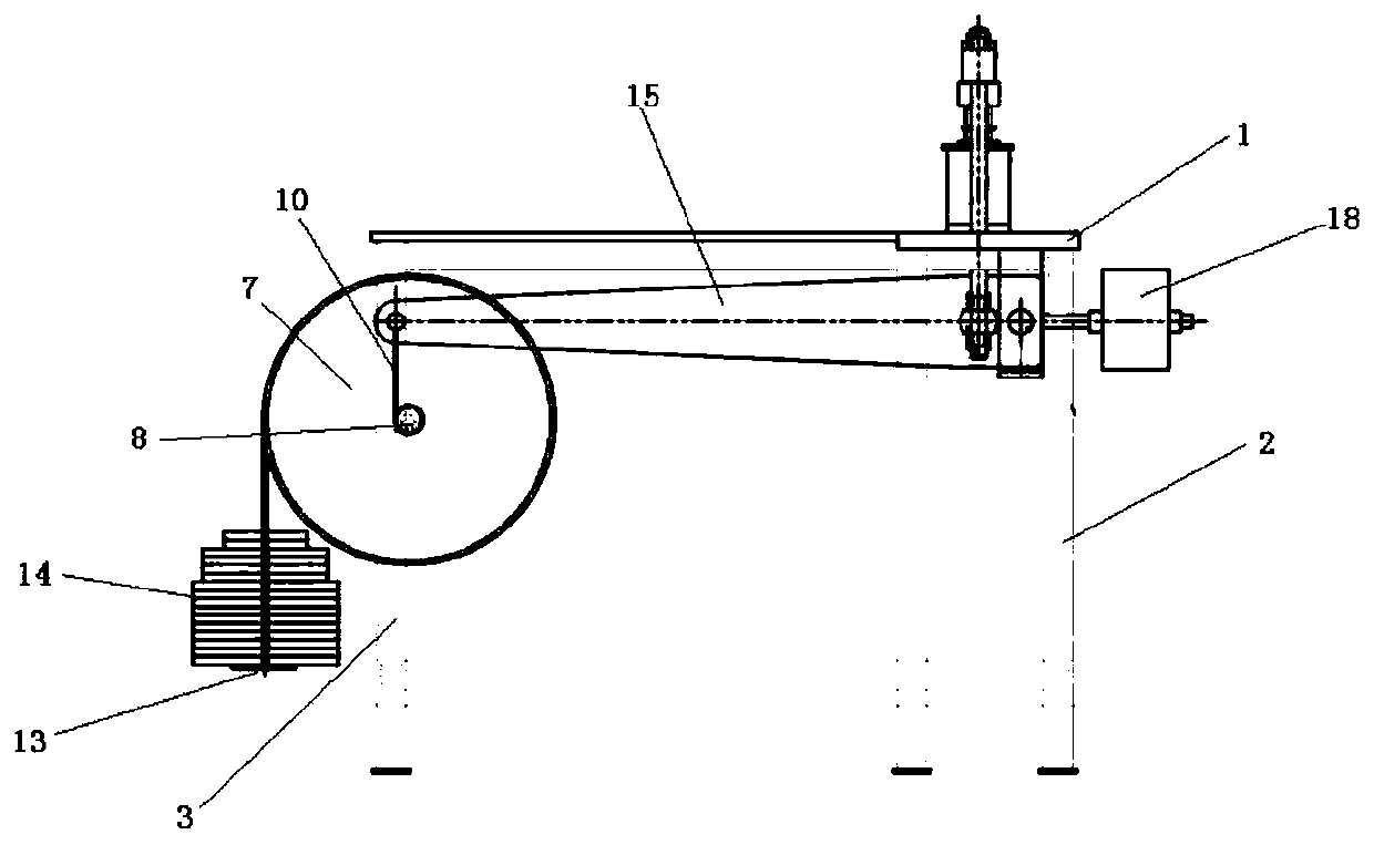
[0033] The device adopted by the invention to solve the technical problem includes a frame part and a test part. The frame part is provided with a rectangular frame plate 1, and one side of the frame plate 1 is provided with four pillars a2, and the other side is provided with two pillars b3. The support of the rack plate 1 by the column b3 is more stable, and the bottom side of the rack plate 1 close to the position of the column b3 is provided with a wheel fixing part 4 perpendicular to the rack plate 1, and one side of the wheel fixing part 4 is arranged in parallel. The roulette 7 and the small roulette 8, and the big roulette 7 and the small roulette 8 are fixed on the roulette fixing part 4 through the shaft, and the axis is perpendicular to the big roulette 7 through the line connecting the center of the circle, and the big roulette 7 and the small roulette 8 is connected by a large bolt 9, the large roulette 7 and the small roulette 8 can rotate and the rotation angles...

Embodiment 2

[0035]Pressure-related calculations for rock samples:

[0036] The radius ratio of the large wheel to the small wheel is 10:1; the leverage ratio is 15:1; the lever and wheel set can amplify the force by 150 times.

[0037] For example: the diameter of the rock sample is 50mm, and the weight is 80kg.

[0038] The pressure obtained for the rock sample is:

[0039] Calculation principles related to instrument design:

[0040] 1. 40Cr steel quenched and tempered diameter ≤ 100mm

[0041] Yield limit 550MPa, safety factor 1.4

[0042] Allowable normal stress:

[0043] Allowable shear stress:

[0044] 2. Spindle:

[0045] (1) Shear strength:

[0046] So d>3.36cm

[0047] (2) Bending strength:

[0048] so

[0049] Namely: ① When l=20cm, d>5.8cm;

[0050] ② When l=25cm, d>6.24cm;

[0051] ③ When l=30cm, d>6.63cm;

[0052] ④ When l=40cm, d>7.3cm.

[0053] A is the cross-sectional area, F is the shear force, W is the axial torsional section modulus; M max is ...

Embodiment 3

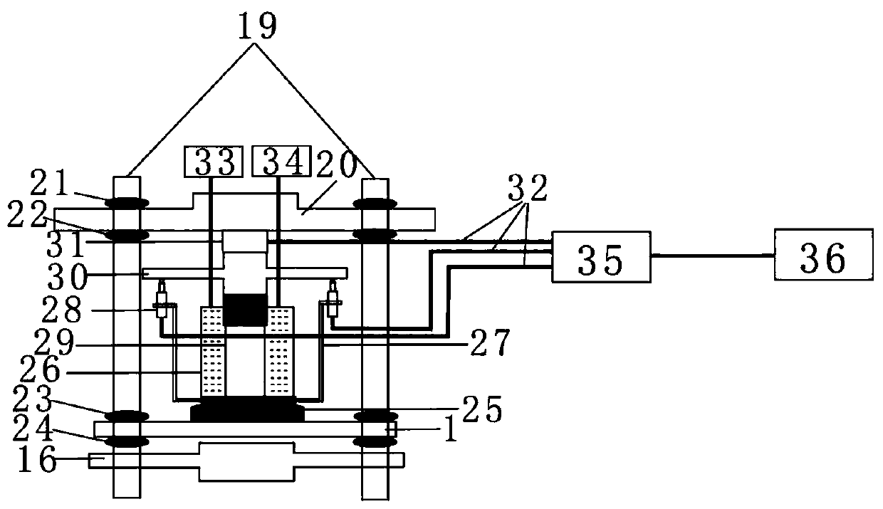
[0097]During the test, the environmental chamber 26 is first placed on the base 25. The contact surface between the base 25 and the environmental chamber 26 is a hemispherical surface, and the balance can be automatically adjusted when the force is applied. Put it on the rock sample 29, adjust the nut b22 to move the beam 20 downward, press the load cell 31 on the rock sample 29, turn the nut a21 downward, and fix the beam 20. Adjust the nut d24 downward, and then adjust the nut c23 upward. The distance between the nut c23 and the rack plate 1 is about 3mm. Adjust the balance weight 18 to balance the lever 15, and finally adjust the nut d24 to make it contact with the bottom of the rack plate 1. touch. Open the acquisition instrument 35 and the computer 36 to display the interface of the load sensor 31 and the size of the LVDT28, then put the LVDT28 fixed on the LVDT frame 27 on the indenter 30, adjust the LVDT28 to the measurable range by the data displayed by the computer 36...


PUM

PropertyMeasurementUnit
diameteraaaaaaaaaa

Abstract

The invention discloses a rock creep test method and device under the action of multiple environments, and belongs to the technical field of rock mechanics tests. The device adopted by the invention comprises a rack part and a test part. The rack part is provided with a rack plate, columns are arranged on the bottom side of the rack plate, a large wheel disc and a small wheel disc are integrally arranged on the bottom side of the rack plate, and weights are connected to the periphery of the large wheel disc. The periphery of the small wheel disc is connected with a lever through a hinge chain,a balance weight is arranged at the other end of the lever, a shaft a fixing component is arranged on the bottom side of the rack plate, and the lever is connected with the shaft a fixing component through a shaft a; the test part is provided with a base, the base is arranged on the upper surface of the rack plate on the column a side; an environment box is arranged on the base, a rock sample isarranged in the environment box, a pressure head is arranged above the rock sample, the side surface of the base is connected with one side of an LVDT frame, the other side of the LVDT frame is connected with an LVDT, the top end of the LVDT is connected with the bottom side of the pressure head, a load sensor is arranged above the pressure head, and a cross beam is arranged above the load sensor.The lever principle and the wheel set transmission principle are used for jointly amplifying the multiple of force, and pressure is applied to a rock sample through weights.

Description

technical field [0001] The invention belongs to the technical field of rock mechanics tests, and relates to a multiphase coupled creep test method and device for rocks under continuous pressure. [0002] technical background [0003] Since the 1930s, experimental research on rock creep properties has been very active. In rock mass engineering, there are a large number of damages caused by rock creep deformation in engineering disasters such as open-pit mine slope landslides, underground mine tunnel collapse, foundation instability, nuclear waste geological storage warehouse rupture, and mine pillar rockburst. Therefore, the test of rock creep characteristics is of great significance to the long-term stability maintenance of rock mass engineering structures. The creep failure of rock is significantly affected by environmental factors and load levels, and sometimes it may take weeks, months or even longer to reach creep failure. Due to the limited test time scale under actual...

Claims


Application Information

Patent Timeline
Patent Type & Authority Applications(China)
IPC IPC(8): G01N3/14
CPCG01N3/14
Inventor 唐世斌李佳明张拥军张永亮
Owner DALIAN UNIV OF TECH
Why Eureka
Try Eureka