
Manufacturing method of passive coupling induction coil

The technology of an induction coil and a manufacturing method, which is applied in the field of passive coupling induction coil manufacturing, can solve problems such as difficult positioning and stable fixing of capacitors, difficulty in disassembly and maintenance, and reduction of production efficiency and production quality of induction coils, so as to improve production efficiency , Simplify the production process and production difficulty, improve production efficiency and production quality

Inactive Publication Date: 2020-07-17
黄友梅
View PDF0 Cites 0 Cited by
  • Summary
  • Abstract
  • Description
  • Claims
  • Application Information

AI Technical Summary

Problems solved by technology

[0003] Traditional passive coupling induction coils are often manufactured manually. Due to the coordination between the coil frame and the capacitor’s activities, the use of glue for bonding makes it difficult to position and stably fix the capacitor on the coil frame. At the same time, the capacitor is fixed on the coil frame. It is difficult to disassemble and repair after installation, which greatly reduces the production efficiency and production quality of the induction coil

Method used


Image

  • Manufacturing method of passive coupling induction coil
  • Manufacturing method of passive coupling induction coil
  • Manufacturing method of passive coupling induction coil

Examples


Embodiment approach

[0035] As an embodiment of the present invention, a layer of elastic layer 3 is provided on the bottom surface of the card slot 14, and the top surface of the elastic layer 3 is set as an arc-shaped surface matched with the side of the arc-shaped plate 22; A layer of elastic layer 3 is provided on the bottom surface of the slot 14. When the bottom end of the arc-shaped plate 22 is pressed into the inside of the slot 14, the arc-shaped plate 22 simultaneously squeezes the elastic layer 3 at the bottom end. 22 and the locking rod 16 are locked together, at this time, the elastic layer 3 exerts a force on the arc-shaped plate 22 under the effect of its own rebound force and makes the locking rod 16 and the second locking groove 23 on the arc-shaped plate 22 The side wall is contacted and pressed to reduce the shaking of the No. 2 locking groove 23 on the arc plate 22 relative to the locking rod 16, and increase the stability of the capacitor 2 on the arc plate 22 when it cooperate...


PUM


Abstract

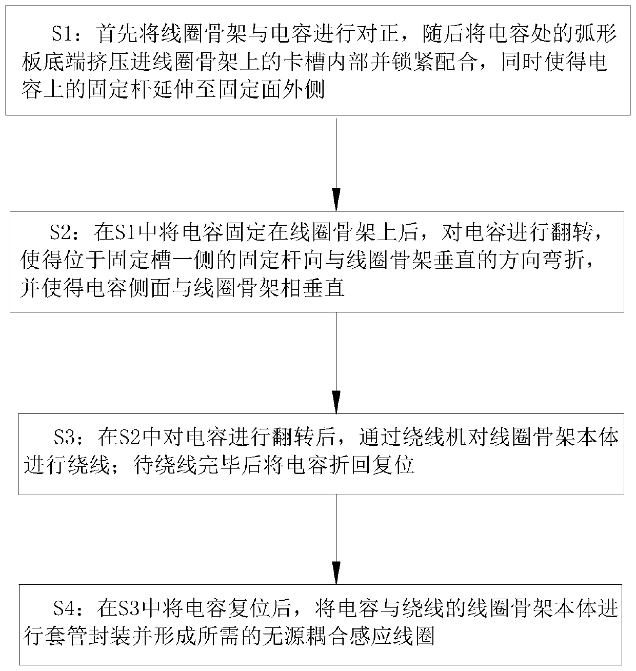
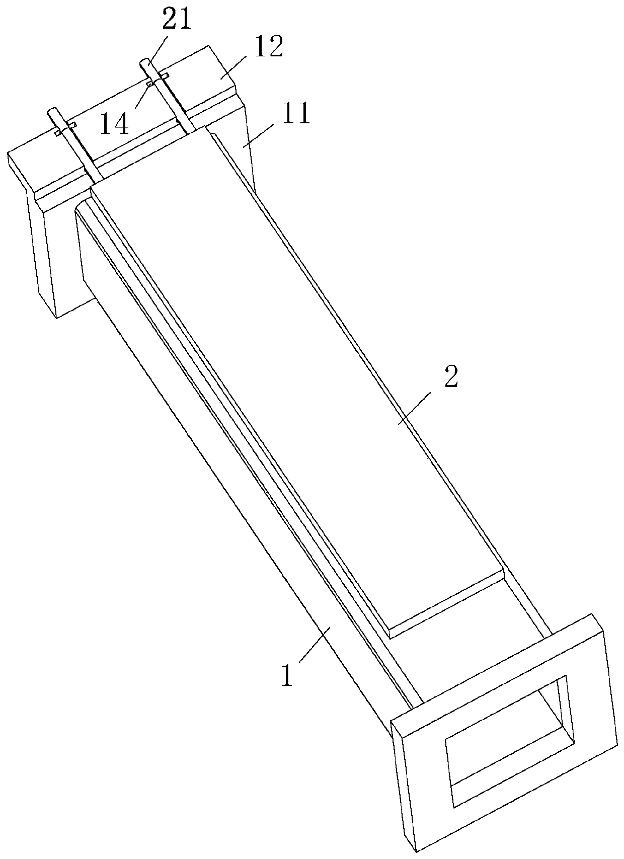
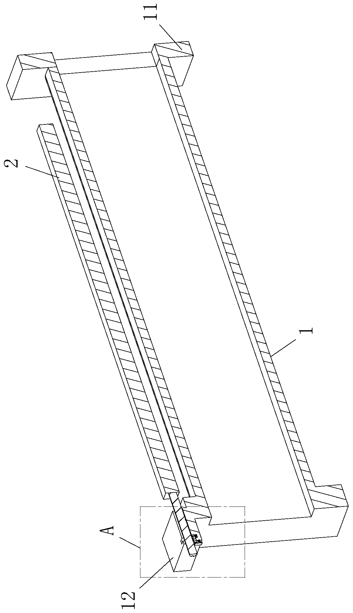
The invention belongs to the technical field of induction coil manufacturing, and particularly relates to a manufacturing method of a passive coupling induction coil. A coil framework in the method comprises a body, step plates are arranged at the two ends of the body, and a fixed surface is arranged on the side surface of each step plate. A fixing groove is formed on the end surface of the fixingsurface, a clamping groove is formed in the fixing groove, and a first locking groove is formed at the bottom end of the clamping groove. A locking rod is slidably connected into the first locking groove, a capacitor is arranged at one side of the body and is connected with a fixing rod, an arc-shaped plate is connected to the end of the fixing rod, and a second locking groove is formed at the bottom end of the arc-shaped plate. According to the induction coil, the capacitor and the coil framework are provided with the locking structures which are matched with each other, so that the complexity and instability of the coil framework and the capacitor during assembly in the production process are reduced, the coil framework and the capacitor can be effectively disassembled and maintained, and the production efficiency and the production quality of the induction coil are improved.

Description

technical field [0001] The invention belongs to the technical field of induction coil manufacturing, in particular to a manufacturing method of a passive coupling induction coil. Background technique [0002] The existing passive coupling induction coil has the following structure: a coil frame, a capacitor, and a coil. The winding end of the coil frame is provided with a winding slot, and the two ends of the coil are wound on two pins of the capacitor, and the pins are placed in the winding slot. , during production, the production sequence is as follows: winding on the automatic winding machine, then manually adding capacitors and wrapping the feet, then manually wrapping the wires and capacitor pins to cut off the excess length of the pins, and then performing manual soldering, manual Sleeve and dry. [0003] Traditional passive coupling induction coils are often manufactured manually. Due to the coordination between the coil frame and the capacitor’s activities, the use...

Claims


Application Information

Patent Timeline
IPC IPC(8): H01F41/098H01F38/14H01F27/40
CPCH01F27/40H01F38/14H01F41/098
Inventor 黄友梅张文龙周浩
Owner 黄友梅
Learn More