Ka-waveband phased array antenna and self-calibration method thereof

A phased array antenna and self-calibration technology, applied to antennas, electrical components, etc., can solve the problems of low service life and high power consumption, and achieve the effect of simplifying the design

Active Publication Date: 2020-07-17
SICHUAN HUIYING PHOTOELECTRIC TECH CO LTD
View PDF6 Cites 7 Cited by
  • Summary
  • Abstract
  • Description
  • Claims
  • Application Information

AI Technical Summary

Problems solved by technology

However, because most of the existing phased array antennas adopt the method of full-array pulse transmission and reception, not only the power consumption is high, but also the service life is low

Method used


Image

  • Ka-waveband phased array antenna and self-calibration method thereof
  • Ka-waveband phased array antenna and self-calibration method thereof
  • Ka-waveband phased array antenna and self-calibration method thereof

Examples


Embodiment 1

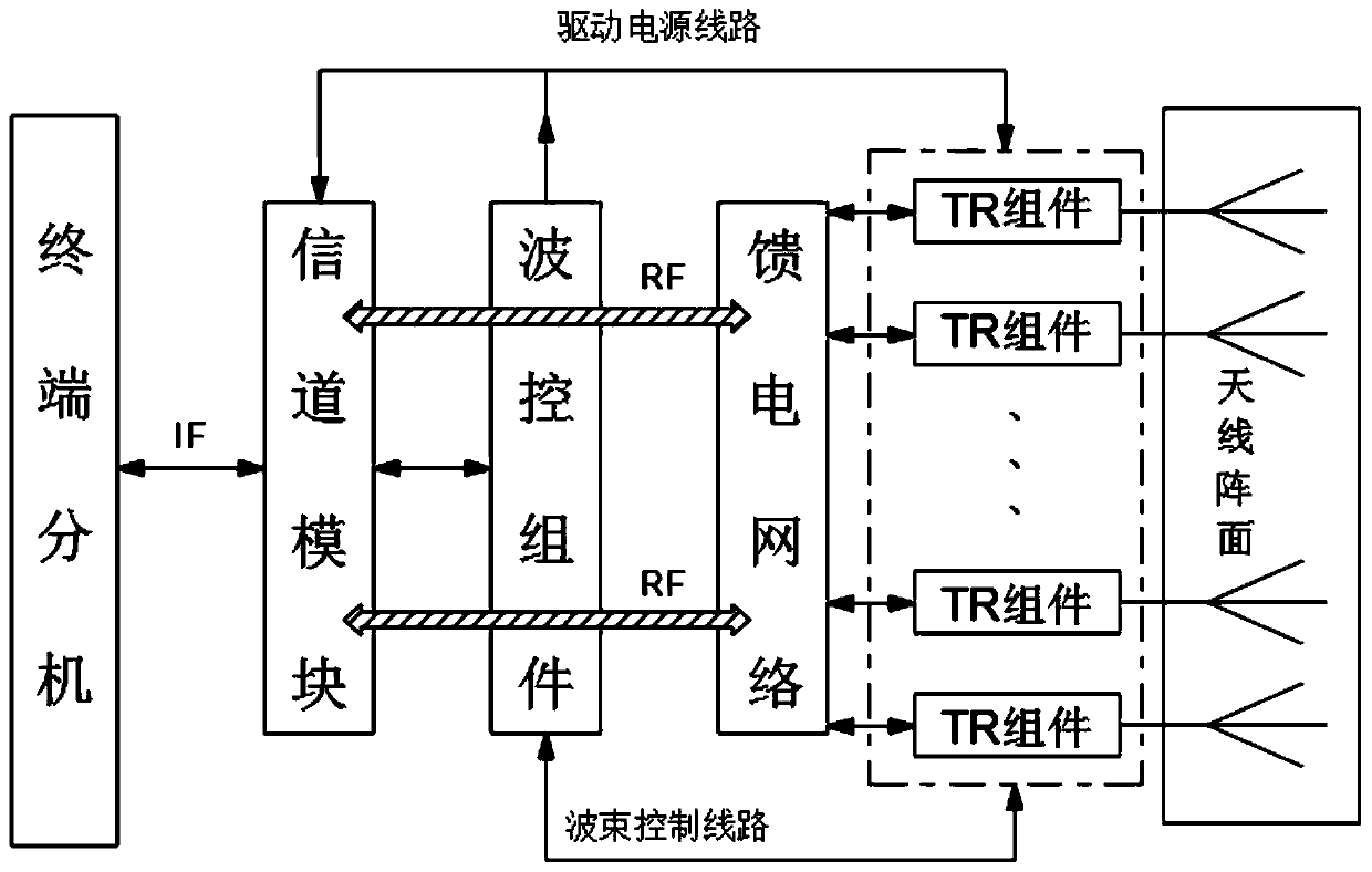
[0061] A phased array antenna of the Ka band is disclosed in this embodiment, such as figure 1 As shown in the architecture diagram, it mainly includes an antenna component 4, a TR component 5, a feed network and a channel component 8, and a plurality of TR modules included in the TR component 5 form a transceiver channel corresponding to the antenna component 4;

[0062] When the channel component 8 receives the input signal, it is converted into a radio frequency signal and distributed into the corresponding TR module through the feed network, and is sent out by the antenna component 4 after phase and amplitude adjustment by the TR module; when the antenna component 4 The received echo signal is processed by the TR component 5 and enters the channel component 8 through the feed network, and is output by the channel component 8; it also includes receiving external beam pointing information and controlling the antenna component 4 and TR component 5 to adjust the beam parameters...

Embodiment 2

[0066] This embodiment also discloses a Ka-band phased array antenna, and the structure is also as figure 1 As shown, it mainly consists of antenna array, multiple TR modules, feed network, beam steering (power module integrated in beam steering) and channel module. The channel module assembly in this embodiment serves as the interface end of the entire antenna, and is provided with a control interface, a radio frequency interface and a power supply interface.

[0067] The radio frequency signal enters the channel module through the radio frequency interface, after being converted by the up-conversion circuit in the channel module, it is directly distributed through the full array feed network and enters the corresponding TR module, and then passes through the phase / amplitude through the transmission link in the TR module Adjust the circuit to ensure the equal amplitude and phase of each transmission path, and finally radiate from the array antenna unit after being amplified b...

Embodiment 3

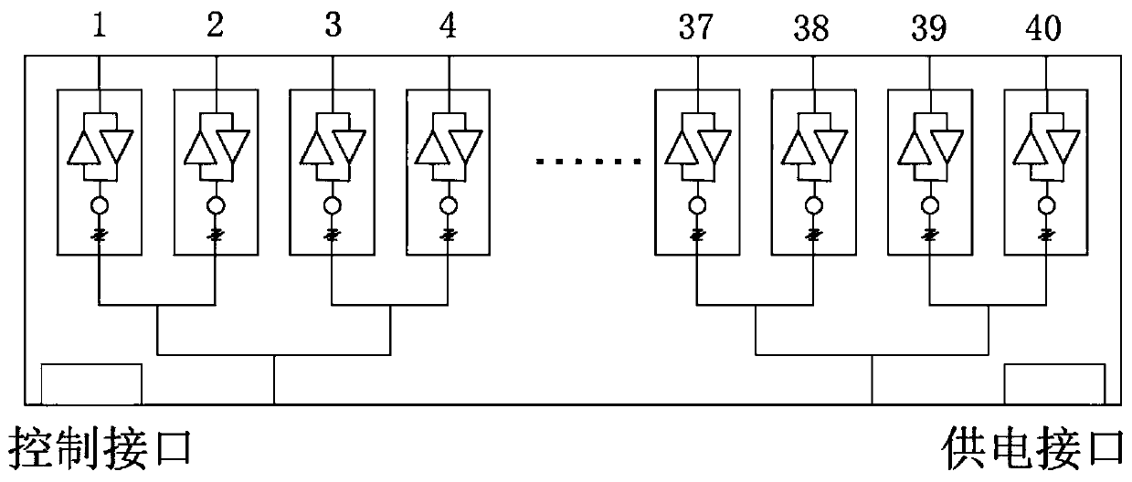
[0083] This embodiment is optimized and limited on the basis of the above-mentioned embodiment 2. First, the original antenna array in this embodiment is equally divided into six sub-arrays, such as Figure 11 As shown, wherein at least one group of sub-arrays is controlled to work in the continuous transmitting and receiving mode. Compared with the above-mentioned embodiment 2, in this embodiment, a TR module is separately arranged for each sub-array, so as to achieve a better control effect.

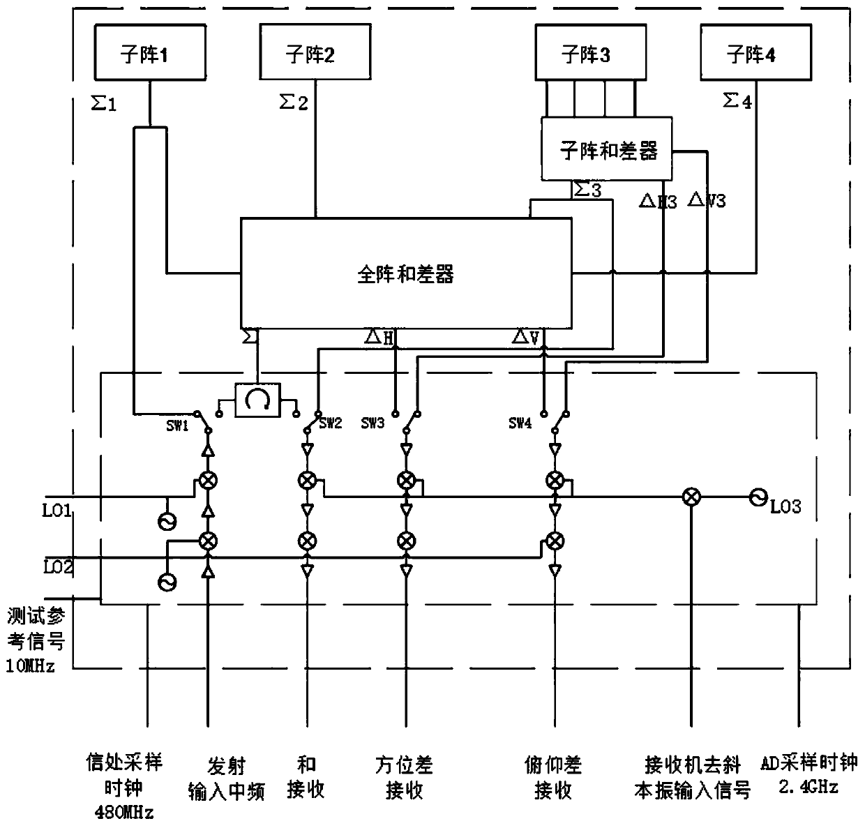
[0084]Moreover, in the continuous receiving mode, any two of the six sub-arrays perform transmitting and receiving work at the same time; while one of the remaining four sub-arrays performs receiving work, the other performs transmitting work, and the remaining two do not work. Or two send and receive at the same time, and the remaining four two receive two transmissions. There is also a separate self-calibration network in the antenna, because of the high pointing accuracy requiremen...


PUM


Abstract

The invention discloses a Ka-waveband phased array antenna, which comprises an antenna assembly and a TR assembly, and is characterized in that a. A plurality of TR modules included in the TR assemblyform a transceiving channel corresponding to the antenna assembly.; the The antenna also comprises a feed network and a channel assembly. The and also comprises a wave control assembly which is usedfor receiving external wave beam pointing information and controlling the antenna assembly and the TR assembly to adjust wave beam parameters; the antenna assembly comprises a plurality of sub-arrays,and the wave control assembly controls part of the sub-arrays to transmit and receive continuously or all the sub-arrays to transmit and receive. According to the invention, aA mode design thought isimplemented, the modular design is carried out on each part, and the one-dimensional / two-dimensional active phased-array antenna can be quickly built by utilizing the shared modules.

Description

technical field [0001] The invention belongs to the technical field of radio frequency antennas, and in particular relates to a Ka-band phased array antenna and a self-calibration method thereof. Background technique [0002] The phased array antenna refers to an antenna that changes the shape of the pattern by controlling the feeding phase of the radiating elements in the array antenna. Controlling the phase can change the direction of the maximum value of the antenna pattern to achieve the purpose of beam scanning. In special cases, it is also possible to control the sidelobe level, the position of the minimum value and the shape of the entire pattern, such as obtaining a cosecant square pattern and performing adaptive control on the pattern, etc. When the antenna is rotated mechanically, the inertia is large and the speed is slow. The phased array antenna overcomes this shortcoming, and the scanning speed of the beam is high. The feeding phase of the antenna is generall...

Claims


Application Information

Patent Timeline
Patent Type & Authority Applications(China)
IPC IPC(8): H01Q3/26
CPCH01Q3/2605
Inventor 文林顺
Owner SICHUAN HUIYING PHOTOELECTRIC TECH CO LTD
Why Eureka
Try Eureka