
Power transmission line without lightning conductor

A technology of transmission lines and lightning protection lines, which is applied in the field of transmission lines without lightning protection lines, can solve problems such as insufficient flow capacity of lightning arresters, influence on the safe operation of the power grid, and inability to apply transmission lines without lightning protection lines, so as to solve the problem of ice-coated disconnection and lightning strikes Troubleshooting problems, enhancing reliability and economy, improving lightning protection and anti-icing performance

Active Publication Date: 2020-07-17
HUNAN XIANGDIAN POWER TEST & RES TECH LTD
View PDF14 Cites 0 Cited by
  • Summary
  • Abstract
  • Description
  • Claims
  • Application Information

AI Technical Summary

Problems solved by technology

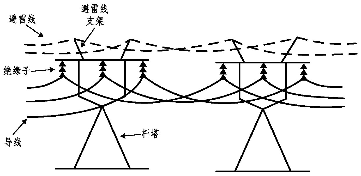
After 2008, although no large-scale freezing disasters occurred, accidents of ice-covered and broken lines of lightning protection lines still occurred frequently, which seriously affected the safe operation of the power grid.
However, due to the parallel installation of lightning arresters and insulators, it is necessary to add additional hanging points on the pole tower, the construction volume is large, the economy is poor, and the insulation coordination is complicated. There have been many times in China that the lightning protection flashover method of line lightning arresters has been canceled due to difficulties in installation and transformation. At the same time, the existing surge arresters have insufficient flow capacity and are easily damaged by direct lightning strikes, so they cannot be applied to transmission lines without lightning arresters

Method used


Image

  • Power transmission line without lightning conductor
  • Power transmission line without lightning conductor
  • Power transmission line without lightning conductor

Examples


Embodiment Construction

[0021] In order to make the purpose, technical solutions and advantages of the embodiments of the present invention clearer, the technical solutions in the embodiments of the present invention will be clearly and completely described below in conjunction with the drawings in the embodiments of the present invention. Obviously, the described embodiments It is a part of embodiments of the present invention, but not all embodiments. Based on the embodiments of the present invention, all other embodiments obtained by persons of ordinary skill in the art without making creative efforts belong to the protection scope of the present invention.

[0022] It should be noted that in this article, relative terms such as "first" and "second" are only used to distinguish one entity or operation from another entity or operation, and do not necessarily require or imply these No such actual relationship or order exists between entities or operations.

[0023] In related technologies, such as ...


PUM


Abstract

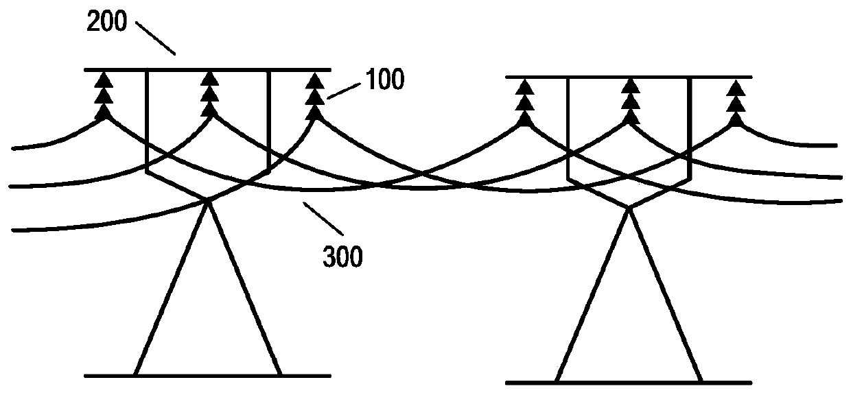
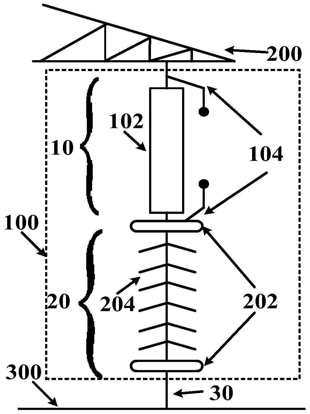
The embodiment of the invention relates to a power transmission line without a lightning conductor. The lightning and ice prevention performance of the power transmission line is enhanced by cancelling the lightning conductor easy to ice and additionally arranging a high-capacity lightning and ice flashover prevention composite insulator. The lightning-conductor-free power transmission line comprises a lightning-protection and anti-icing insulator, a tower, a wire and a communication medium, the through-current capability of the lightning-protection and anti-icing insulator is higher than thatof a traditional lightning arrester, and lightning current can be conducted to the tower while the lightning-protection and anti-icing insulator is used for hanging the wire; and the tower adopts a natural grounding mode and is used for guiding the lightning current into the ground. According to the lightning-conductor-free power transmission line scheme, the problem that a traditional line is prone to ice coating and line breaking of a lightning conductor is solved, the lightning protection and ice prevention performance of the power transmission line is improved, meanwhile, the constructioncost of the power transmission line is reduced, and the economy and reliability of the power transmission line are improved.

Description

technical field [0001] The invention relates to the field of power transmission, in particular to a power transmission line without lightning protection wires. Background technique [0002] With the rapid development of electric power construction, the area covered by the power grid is getting wider and wider, and transmission lines often need to be erected in some mountainous areas with complex terrain, and these areas often have climate phenomena that are prone to ice in winter and frequent lightning in spring and summer. In the above-mentioned special geographical environment areas, when encountering severe weather, the transmission line is prone to icing flashover or lightning flashover, which will cause tripping and blackout accidents, which seriously threatens the safe and stable operation of the large power grid. [0003] In the transmission line, the lightning protection wire is used to prevent the excessive lightning current from directly hitting the wire, and plays...

Claims


Application Information

Patent Timeline
Patent Type & Authority Applications(China)
IPC IPC(8): H02G7/20H02G7/22H02G7/16
CPCH02G7/16H02G7/20H02G7/22
Inventor 陆佳政谢鹏康胡建平方针吴伟蒋正龙
Owner HUNAN XIANGDIAN POWER TEST & RES TECH LTD
Learn More