Ultrasonic out-of-plane blood vessel puncture auxiliary robot

A robot, out-of-plane technology, applied in the field of medical devices, can solve the problems of puncture failure, inability to clarify the positional relationship of the needle tip, and puncture needle detachment, etc., to achieve the effect of improving the puncture success rate and avoiding the risk of complications

Active Publication Date: 2020-07-21
BEIJING INSTITUTE OF TECHNOLOGYGY
View PDF4 Cites 4 Cited by
  • Summary
  • Abstract
  • Description
  • Claims
  • Application Information

AI Technical Summary

Problems solved by technology

[0003] In-plane technology, the puncture needle is always in the scanning plane of the probe, and the needle insertion route can be fully displayed during the puncture process. The disadvantage is that the surrounding tissue cannot be observed, and the probe operation is unstable and blood vessels are easily lost, and it cannot be clearly defined due to the volume effect of ultrasound. The positional relationship between the needle tip and the cut surface of the blood vessel caused puncture failure
[0004] The out-of-plane technique can clearly display the anatomical relationship of the surrounding tissues, and the blood vessel information can be easily distinguished in the ultrasound image. The puncture path is short and can ensure that the puncture needle is in the middle of the top of the blood vessel, and the puncture success rate is high. The disadvantage is that the needle body and needle tip are not visible during the puncture process. , it is easy to cause the risk of puncture complications. When the puncture needle penetrates into the blood vessel and reduces the puncture angle, it is easy to cause problems such as detachment of the puncture needle and puncture of the blood vessel.

Method used


Image

  • Ultrasonic out-of-plane blood vessel puncture auxiliary robot
  • Ultrasonic out-of-plane blood vessel puncture auxiliary robot
  • Ultrasonic out-of-plane blood vessel puncture auxiliary robot

Examples


Embodiment Construction

[0019] In order to make the purpose, technical solutions and advantages of the embodiments of the present invention clearer, the technical solutions in the embodiments of the present invention will be clearly and completely described below in conjunction with the drawings in the embodiments of the present invention. Obviously, the described embodiments It is a part of the embodiments of the present invention, but not all of them. Based on the embodiments in the embodiments of the present invention, all other embodiments obtained by persons of ordinary skill in the art without making creative efforts belong to the protection scope of the embodiments of the present invention.

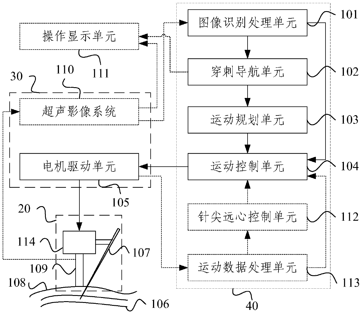
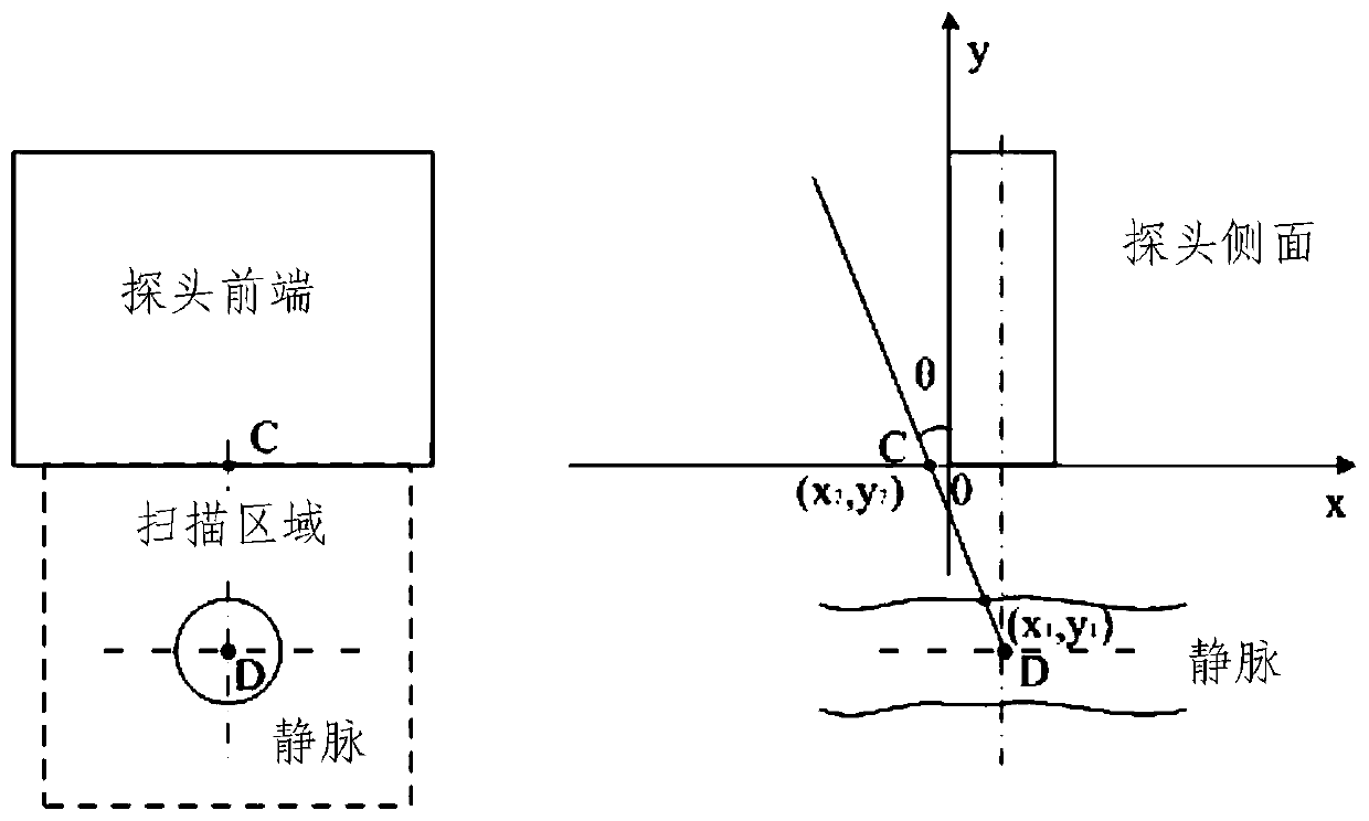
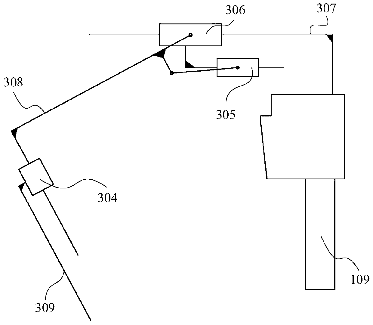
[0020] The embodiment of the present invention aims at the problems in the prior art that the position of the needle body and the needle tip is difficult to determine during the out-of-plane puncture process, and puncture complications are prone to occur, etc., realizes precise control of the puncture need...


PUM


Abstract

The embodiment of the invention provides an ultrasonic out-of-plane blood vessel puncture auxiliary robot which comprises an image recognition processing unit used for analyzing and calculating a blood vessel real-time image of a puncture target area and obtaining blood vessel contour shape data and blood vessel center position data; a puncture navigation unit for calculating a preferred punctureposture and a preferred puncture path based on the blood vessel contour shape data and the blood vessel center position data; a motion planning unit used for calculating motor control parameters required for adjusting the puncture needle from the current posture to the optimal puncture posture based on the optimal puncture path; and a motion control unit used for controlling the motor driving unitbased on the motor control parameters, driving the puncture needle to move to the optimal puncture posture and carrying out puncture along the optimal puncture path. Wherein the units are sequentially connected. According to the embodiment of the invention, the complication risk of an out-of-plane puncture technology can be effectively avoided, and the puncture success rate is effectively improved.

Description

technical field [0001] Embodiments of the present invention relate to the technical field of medical devices, and more specifically, relate to an ultrasonic out-of-plane blood vessel puncture assisting robot. Background technique [0002] Ultrasound-guided vascular puncture has the advantages of real-time observation of anatomical structures, puncture paths, shortened puncture time, and reduced puncture complications. There are pros and cons. [0003] In-plane technology, the puncture needle is always in the scanning plane of the probe, and the needle insertion route can be fully displayed during the puncture process. The disadvantage is that the surrounding tissue cannot be observed, the probe operation is unstable and blood vessels are easily lost, and it cannot be clearly defined due to the volume effect of ultrasound. The positional relationship between the needle tip and the cut surface of the blood vessel caused the failure of puncture. [0004] The out-of-plane tech...

Claims


Application Information

Patent Timeline
IPC IPC(8): A61B34/30A61B34/20A61B17/34
CPCA61B17/3403A61B2017/3413A61B34/20A61B34/30A61B2034/2063A61B2034/2065
Inventor 张磊张博张立群张哲明黄强藤江正克
Owner BEIJING INSTITUTE OF TECHNOLOGYGY
Why Eureka
Try Eureka