Prefabricated foundation bearing platform and foundation structure
A foundation and foundation technology, applied in infrastructure engineering, construction, etc., can solve the problems of low construction efficiency, environmental pollution, long cycle, etc., and achieve the effect of shortening construction period, reducing environmental pollution of construction site, and easy connection
- Summary
- Abstract
- Description
- Claims
- Application Information
AI Technical Summary
Problems solved by technology
Method used
Image

Examples
Embodiment 1
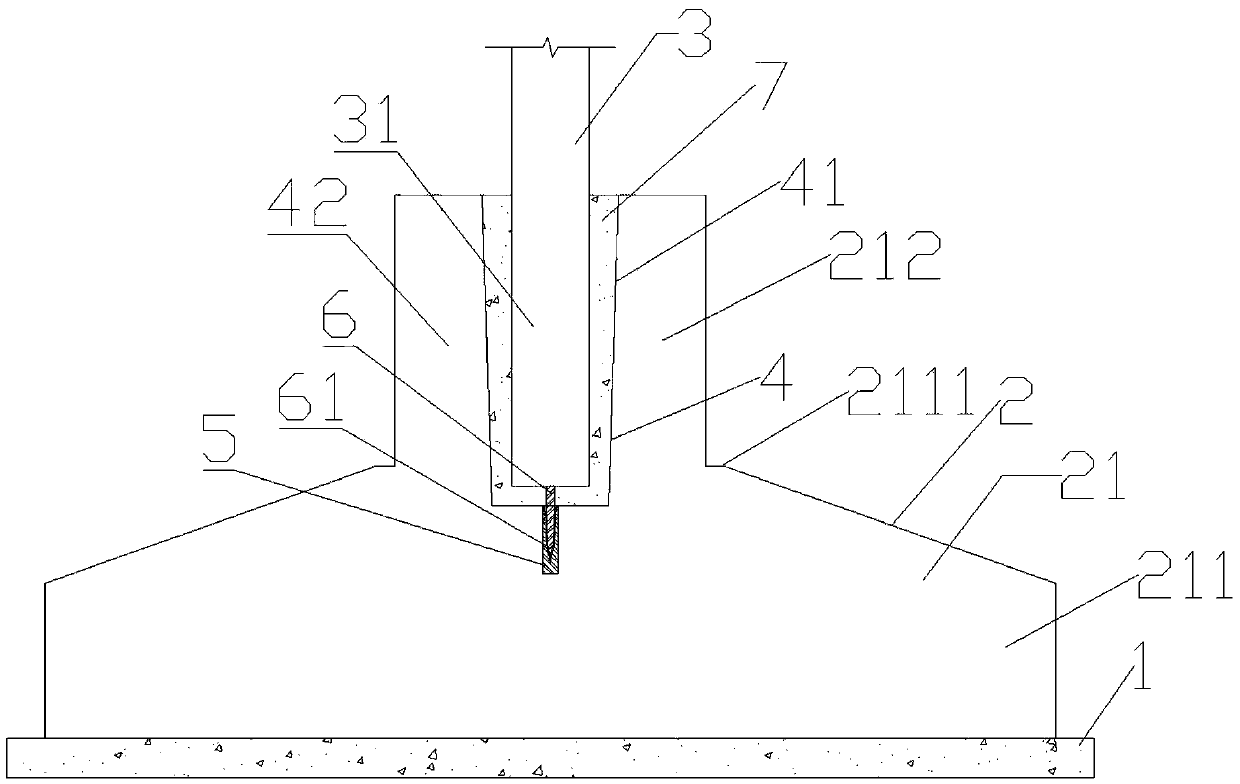
[0042] Such as figure 1 As shown, this embodiment relates to a foundation structure using a prefabricated foundation cap, which sequentially includes a cushion layer 1, a foundation cap 2, and a wall column member 3 from bottom to top. After the cushion layer 1 is laid on the piling, etc.), the prefabricated foundation cap 2 is placed, and then the wall column member 3 is fixedly installed on the foundation cap 2, wherein the joint part of the wall column component 3 and the foundation cap 2 The concrete body is poured for reinforcement, so that the assembled structure of the wall column member 3 and the foundation cap 2 can be realized, thereby improving construction efficiency and reducing construction pollution. The components of the above-mentioned foundation structure will be further described in detail below.
[0043] Cushion 1 is an intermediate layer between the foundation cap 2 (i.e. concrete foundation) and the foundation soil, and its specific structure can be a cu...
Embodiment 2
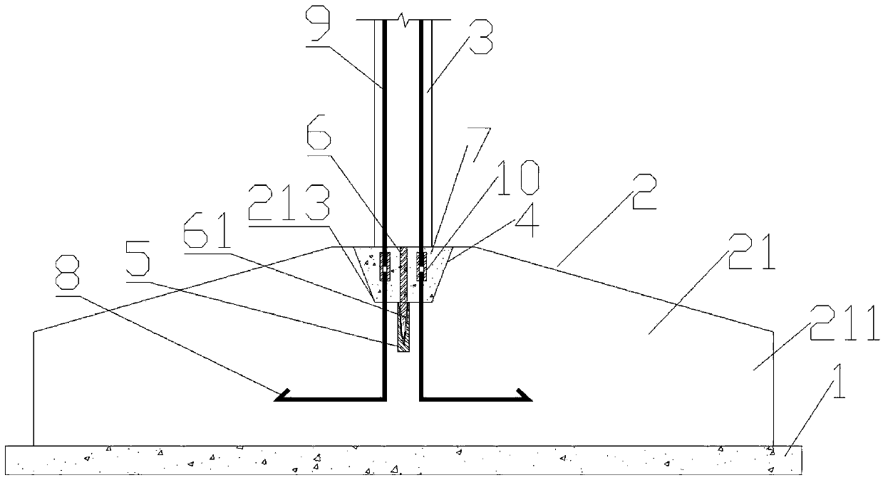
[0054] In this example, no figure 1 The similar platform socket body 42 is not convenient to form a socket recess with sufficient depth, so the wall column member 3 and the foundation platform 2 do not adopt a socket structure, but are connected by anchor ribs, that is, through the wall The column member 3 and the foundation cap 2 are provided with an anchoring rib structure to increase connection reliability. other parts can be used figure 1 In the scheme, the same parts as in Embodiment 1 are given the same reference numerals, and the same text descriptions are omitted.
[0055] Such as figure 2 As shown, compared with Embodiment 1, the connecting portion 4 of the prefabricated foundation cap 2 in this embodiment is set as a groove provided on the cap base 21, and the groove is an inverted trapezoidal groove with a large upper part and a smaller lower part (just for convenience) The pouring is not limited to this shape, it can be any shape that meets the load-bearing and...
Embodiment 3
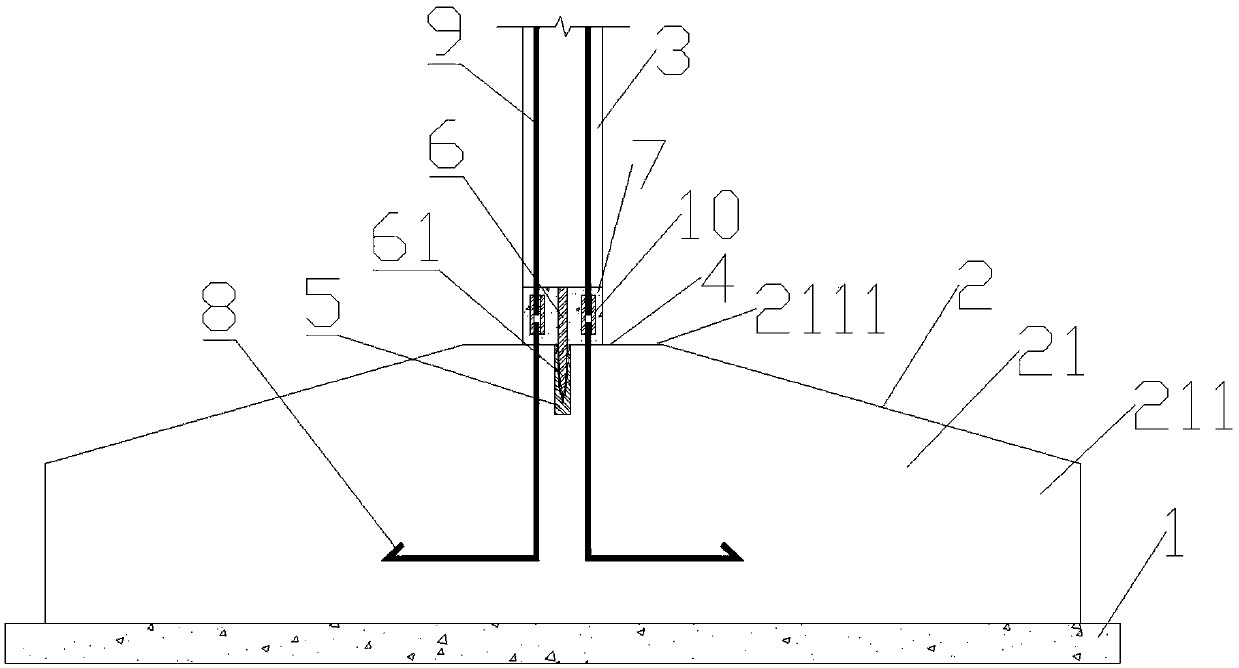
[0060] This embodiment is an alternative to embodiment 2, and the difference from embodiment 2 is that the concrete pouring recess is not provided in the cap connecting portion 4, but the concrete body is directly poured on the top of the cap connecting portion. This embodiment also directly adopts the connection method of anchoring steel bars and pouring concrete, and a number of positioning parts are arranged between the wall column member 3 and the foundation cap 2 for installation and positioning, further description is as follows.
[0061] Such as image 3 As shown, compared with Embodiment 2, the cap connecting part 4 of the prefabricated foundation cap 2 in this embodiment is set as a concrete pouring surface flush with the top surface of the cap base, and the concrete pouring surface is provided with a pouring forming The fixed concrete body 7, the wall column member 3 is carried on the fixed concrete body 7, the positioning support rod 6 at the bottom of the wall colu...
PUM
 Abstract
Description
Claims
Application Information
 - R&D
- Intellectual Property
- Life Sciences
- Materials
- Tech Scout
- Unparalleled Data Quality
- Higher Quality Content
- 60% Fewer Hallucinations
Browse by: Latest US Patents, China's latest patents, Technical Efficacy Thesaurus, Application Domain, Technology Topic, Popular Technical Reports.
© 2025 PatSnap. All rights reserved.Legal|Privacy policy|Modern Slavery Act Transparency Statement|Sitemap|About US| Contact US: help@patsnap.com