Centrifugal fan, extractor hood applying same and control method

A technology of centrifugal fans and range hoods, applied in application, pump control, oil fume removal, etc., can solve problems such as unsatisfactory effects, and achieve the effects of optimizing vortex, reducing lateral flow, and improving secondary flow

Active Publication Date: 2020-07-21
NINGBO FOTILE KITCHEN WARE CO LTD
View PDF9 Cites 2 Cited by
  • Summary
  • Abstract
  • Description
  • Claims
  • Application Information

AI Technical Summary

Problems solved by technology

The effect achieved by this way of shunting is not ideal, and needs to be improved

Method used


Image

  • Centrifugal fan, extractor hood applying same and control method
  • Centrifugal fan, extractor hood applying same and control method
  • Centrifugal fan, extractor hood applying same and control method

Examples


Embodiment 1

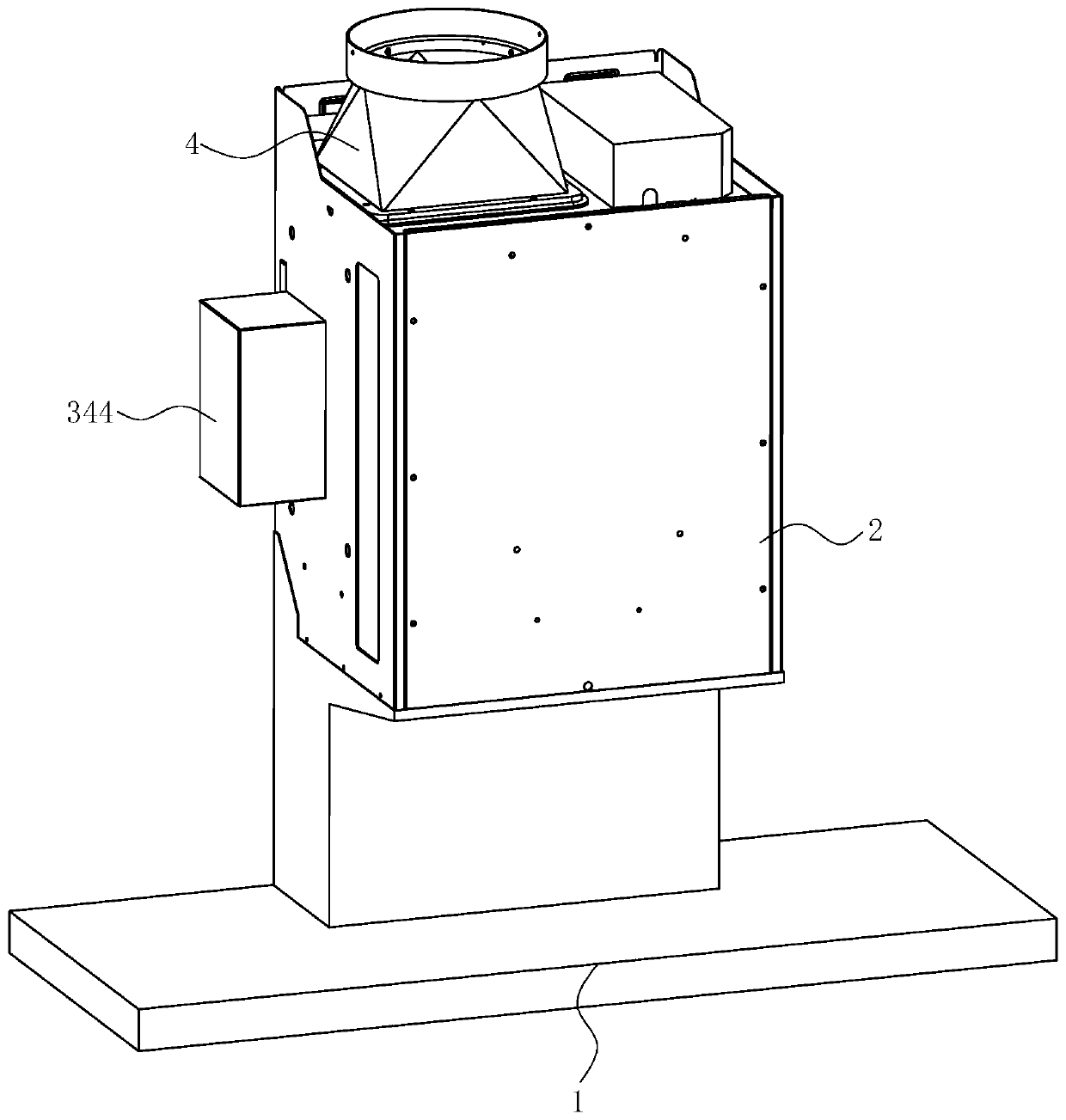
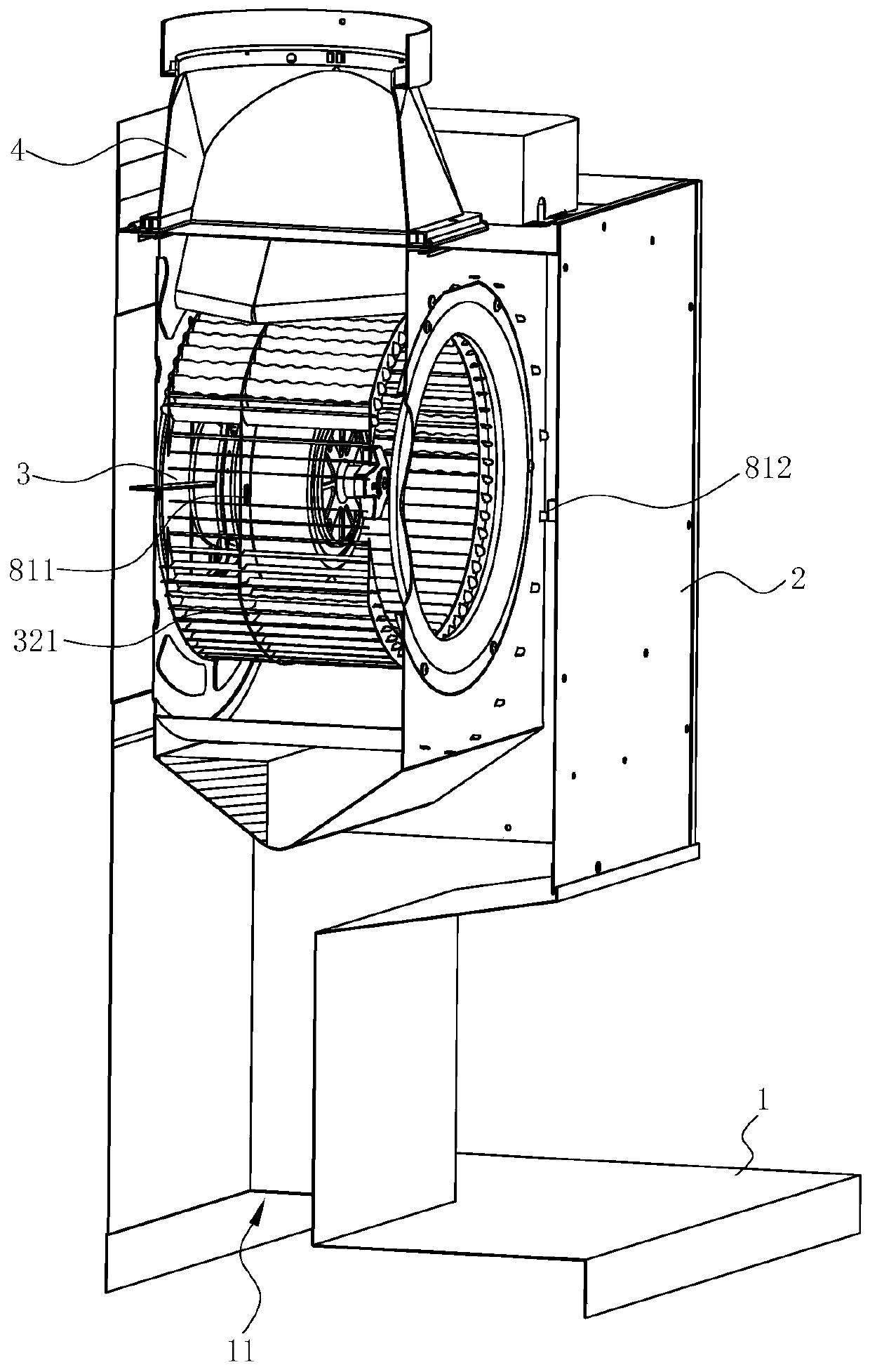
[0048] see Figure 1 to Figure 6, a range hood, comprising a fume collecting hood 1, a casing 2 arranged above the fume collecting hood 1 and a centrifugal fan 3 arranged in the casing 2, and an outlet hood 4 is arranged at the outlet of the centrifugal fan 3. The fume collecting hood 1 is provided with an air inlet 11 . Therefore, under the action of the centrifugal fan 3 , the oil fume is sucked into the inside of the range hood through the air inlet 11 from the lower part of the range hood, and is discharged to the public flue through the air outlet hood 4 .

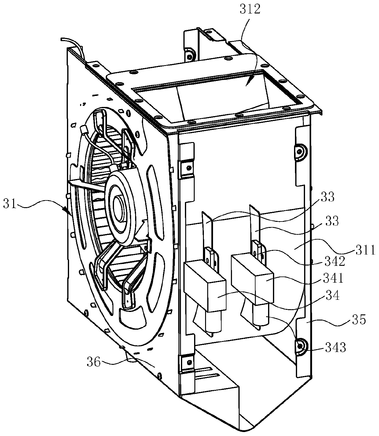
[0049] The centrifugal fan 3 includes a volute 31, an impeller 32 arranged in the volute 31, a front air deflector 35 and a rear air deflector 36. The volute 31 includes a ring wall 311, and the front end of the ring wall 311 is fixed on the front wind deflector 35, The rear end of the ring wall 311 is fixed on the rear wind deflector 36 . The annular wall 311 , the front air deflector 35 and the rear air deflector ...

Embodiment 2

[0061] see Figure 11 to Figure 14 , the top of the air outlet hood 4 is provided with an outlet pipe 5 and communicated with each other. The working condition detection device is a flow velocity measurement device provided on the outlet pipe 5, including a rectifying grille 61 arranged in the outlet pipe 5, a pitot tube 62 arranged on the inner side of the peripheral wall of the outlet pipe 5, and a feedback unit 63 arranged on the peripheral wall of the outlet pipe 5. On the outside, on the oil fume flow path, the pitot tube 62 is located downstream of the straightening grille 61 . The rectifying grille 61 makes the air flow into the outlet pipe 5 and is rectified by the rectifying grille 61, so that the airflow near the pitot tube 62 is uniform and the measurement is more accurate. The pitot tube 62 adopts the prior art, and its outer peripheral wall is provided with a static pressure measurement hole 621 for measuring the static pressure Ps, and the bottom end is provided...

Embodiment 3

[0069] see Figure 16 to Figure 18 , in this embodiment, the difference from the second embodiment is that the working condition detection device is a static pressure measuring device arranged on the outlet pipe 5, including a rectifying grille 61 arranged in the outlet pipe 5, The static pressure pipe 62 ′ on the inner side of the peripheral wall and the feedback unit 63 on the outer side of the peripheral wall of the outlet pipe 5 are located downstream of the rectifying grille 61 on the oil fume flow path. The rectification grid 61 makes the air flow into the outlet pipe 5 and is rectified by the rectification grid 61, so that the air flow near the static pressure pipe 62' is uniform and the measurement is more accurate. The static pressure pipe 62' adopts the prior art, and its outer peripheral wall is provided with a static pressure measuring hole 621' for measuring the static pressure Ps.

[0070] Its control method see Figure 19 , including the following steps:

[0...


PUM


Abstract

The invention discloses a centrifugal fan. The centrifugal fan comprises a volute, the volute comprises a ring wall, and it is characterized in that fairing plates are further included, the positions,on the rear segment of a molded line of the volute, of the fairing plates penetrate through the ring wall from the outer portion of the ring wall to be inserted into the volute, outlines, inserted into the volute and away from the side face of the ring wall, of the fairing plates are consistent with molded lines of the crossing parts of the volute and the fairing plates, an extractor hood applying the centrifugal fan and a control method of the extractor hood are included, and compared with the prior art, the centrifugal fan, the extractor hood applying the same and the control method have the advantages that the fairing plates can damage the vortex center in the volute, transverse flowing of the airflow on the wall face of the volute can be reduced, the secondary flowing in the volute can be improved, the vortex on an outlet is optimized, an automatic adjusting device automatically adjusts the height of the fairing plates according to different working conditions to adapt to airflowflowing under different pipeline resistances, transverse secondary flowing in the volute under the different working conditions can be improved, and the extractor hood has the optimal flowing state under the various working conditions.

Description

technical field [0001] The invention relates to kitchen equipment, in particular to a centrifugal fan, a range hood using the centrifugal fan, and a control method for the range hood. Background technique [0002] The working principle of the centrifugal fan is that the motor drives the impeller to rotate to do work on the airflow, and discharges it from the radial direction through the diffusing effect of the volute. The volute is an important component of the centrifugal fan. The airflow leaving the impeller must be collected and diffused by the volute before it can be conveyed. [0003] Appropriate volute profile design can reduce the loss of airflow in the volute and improve the aerodynamic performance of the centrifugal fan. Due to the different smoke exhaust environment, the household range hood operates under the corresponding working conditions according to the resistance of the outlet flue, and the flow characteristics of the airflow in the fan are different under ...

Claims


Application Information

Patent Timeline
IPC IPC(8): F04D29/44F04D27/00F24C15/20
CPCF04D27/001F04D27/004F04D29/441F24C15/2021
Inventor 郑文鑫边乐超何立博庞广胜
Owner NINGBO FOTILE KITCHEN WARE CO LTD
Why Eureka
Try Eureka