Bone drill bit and base mounting method

A bone and drill technology, applied in the field of medical devices, can solve the problems of easy deformation of the base, achieve long-term effective fixation, improve stability, and facilitate incision healing

Pending Publication Date: 2020-07-24
SHINEYARD MEDICAL DEVICE CO LTD
View PDF0 Cites 0 Cited by
  • Summary
  • Abstract
  • Description
  • Claims
  • Application Information

AI Technical Summary

Problems solved by technology

[0004] The purpose of the present invention is to provide a bone drill bit to solve the technical problems that there are gaps when the existing base is fixed on the surface of the bone, and the base is easily deformed

Method used


Image

  • Bone drill bit and base mounting method
  • Bone drill bit and base mounting method
  • Bone drill bit and base mounting method

Examples


Embodiment 1

[0098] A bone drill bit 10 includes a positioning component 11 and a milling component 12 .

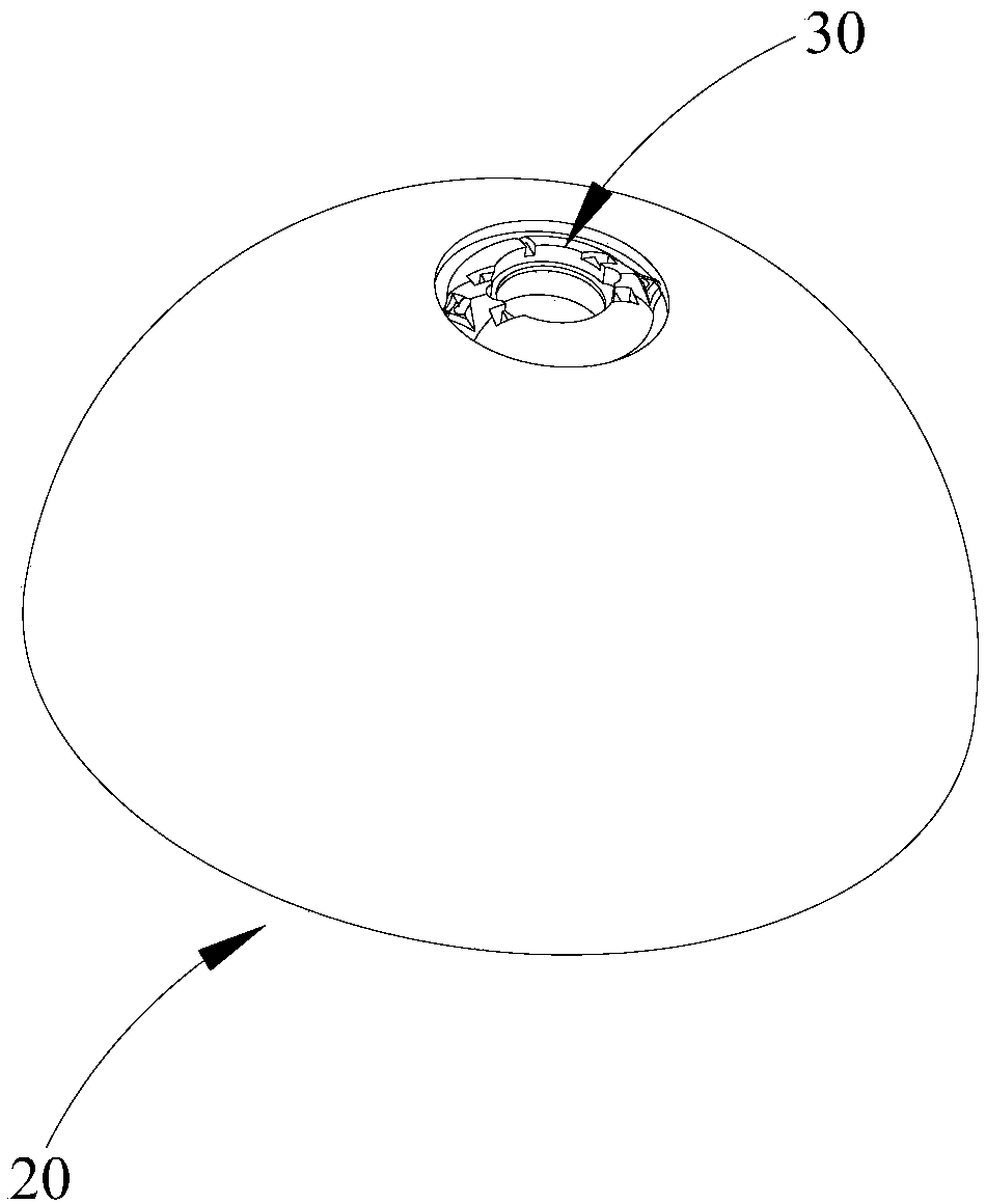
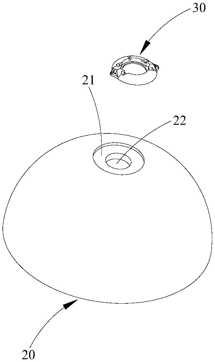
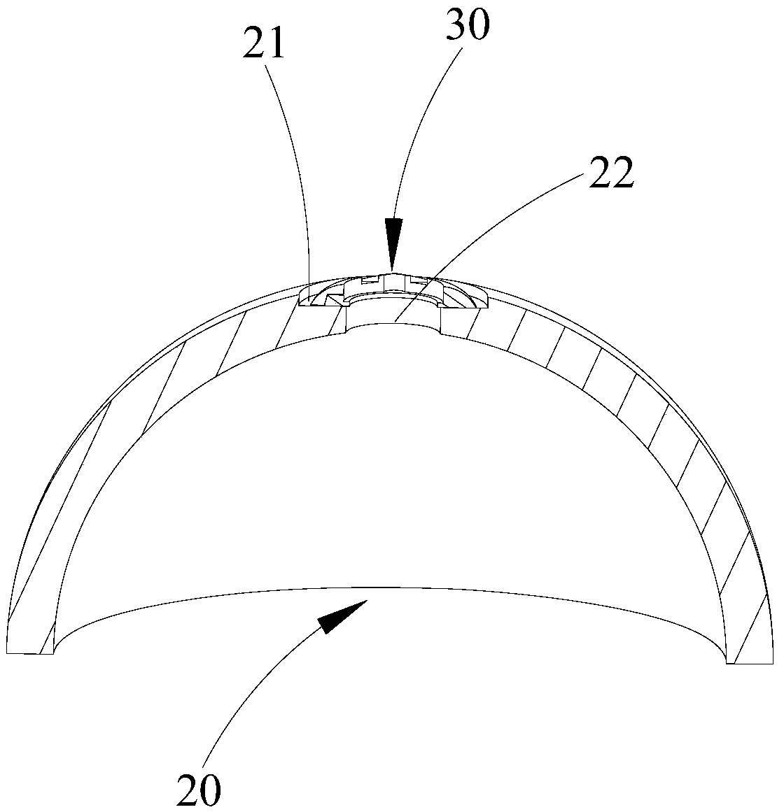
[0099] The positioning assembly 11 includes a positioning boss 111, which is used to be arranged in the pre-opened installation hole 22 of the skull 20, and the diameter of the positioning boss 111 is 10mm-16mm.

[0100] The milling assembly 12 includes a milling edge 121 and a clamping portion 122. The milling edge 121 includes a first bottom plate 1211 and a plurality of first blades 1212. The clamping portion 122 and the positioning boss 111 are respectively arranged on opposite side surfaces of the first bottom plate 1211. . For the convenience of description, the opposite side surfaces of the first base plate 1211 are respectively marked as the upper surface of the first base plate and the lower surface of the first base plate, wherein the clamping portion 122 is connected to the upper surface of the first base plate, and the positioning boss 111 is located on the first base plat...

Embodiment 2

[0103] A bone drill bit 10 includes a positioning component 11 and a milling component 12 .

[0104] The positioning assembly 11 includes a positioning boss 111, which is used to be arranged in the pre-opened installation hole 22 of the skull 20, and the diameter of the positioning boss 111 is 10mm-16mm.

[0105] The milling assembly 12 includes a milling edge 121 and a clamping portion 122. The milling edge 121 includes a first bottom plate 1211 and a plurality of first blades 1212. The clamping portion 122 and the positioning boss 111 are respectively arranged on opposite side surfaces of the first bottom plate 1211. . For the convenience of description, the opposite side surfaces of the first base plate 1211 are respectively marked as the upper surface of the first base plate and the lower surface of the first base plate, wherein the clamping portion 122 is connected to the upper surface of the first base plate, and the positioning boss 111 is located on the first base plat...

Embodiment 4

[0115] A bone drill bit 10 includes a positioning component 11 and a milling component 12 .

[0116] The positioning assembly 11 includes a positioning boss 111, which is used to be arranged in the pre-opened installation hole 22 of the skull 20, and the diameter of the positioning boss 111 is 10mm-16mm.

[0117] The milling assembly 12 includes a milling edge 121 and a clamping portion 122. The milling edge 121 includes a first bottom plate 1211 and a plurality of first blades 1212. The clamping portion 122 and the positioning boss 111 are respectively arranged on opposite side surfaces of the first bottom plate 1211. . For the convenience of description, the opposite side surfaces of the first base plate 1211 are respectively marked as the upper surface of the first base plate and the lower surface of the first base plate, wherein the clamping portion 122 is connected to the upper surface of the first base plate, and the positioning boss 111 is located on the first base plat...


PUM


Abstract

The invention relates to the technical field of medical instruments, and provides a bone drill bit and a base mounting method. The bone drill bit comprises a positioning assembly and a milling assembly; the positioning assembly comprises a positioning boss, and the positioning boss is used for being arranged in a mounting hole formed in the bone in advance; the milling assembly comprises a millingknife edge and a clamping part, the clamping part is connected with the milling knife edge, and the milling knife edge is connected with the positioning boss; the clamping part is used for being connected with an external power device and driving the milling knife edge to rotate under the action of the external power device; and the bone drill bit can mill an installation surface around the installation hole, the shape of the installation surface is matched with the shape of the bottom surface of a DBS base, the installation surface can be completely attached to the bottom surface of the DBSbase, and the fixing effect is better. In the fixing process, the DBS base does not deform, subsequent fixing of an electrode locking device is facilitated, and then the stability of the DBS electrodewire can be improved.

Description

technical field [0001] The invention relates to the technical field of medical instruments, and more specifically, relates to a bone drill bit and a base installation method. Background technique [0002] Deep Brain Stimulation (Deep Brain Stimulation, abbreviated as DBS), also known as brain pacemaker surgery, has developed into an alternative to the traditional brain stereotaxic functional surgery in the past 20 years. . DBS technology is to implant electrodes in specific nerve nuclei in the brain through brain stereotaxic technology, inhibit abnormal neurons and their fibers through high-frequency electrical stimulation, reduce the state of excessive neuronal excitation in patients, and make the inner environment of the nerves tend to be more stable. Normal, stable, and then achieve the purpose of treating diseases. [0003] At present, the DBS electrode lead is fixed on the base by stimloc (electrode locking device), and the base is fixed on the surface of the skull. ...

Claims


Application Information

Patent Timeline
Patent Type & Authority Applications(China)
IPC IPC(8): A61B17/16
CPCA61B17/1615A61B17/1695A61B2017/1602A61B2017/564
Inventor 项威王浩汪郁卉徐勇李午阳
Owner SHINEYARD MEDICAL DEVICE CO LTD
Why Eureka
Try Eureka