Assembly machine and assembly method

A technology of assembling machine and frame, which is applied in the field of mechanical processing, and can solve the problems of unfavorable L-shaped steel plate assembling, mutual movement of bottom plate and side plate, and achieve the effect of improving assembly accuracy and avoiding offset

Pending Publication Date: 2020-07-24
CHINA CONSTR STEEL STRUCTURE ENG CO LTD
View PDF0 Cites 0 Cited by
  • Summary
  • Abstract
  • Description
  • Claims
  • Application Information

AI Technical Summary

Problems solved by technology

With the continuous change of production demand, there are different types of steel plates, such as L-shaped steel plate, but because the side plate of L-shaped steel plate needs to be placed on one side of the bottom plate, if the L-shaped steel plate is clamped by the telescopic clamping device on both sides Clamping and positioning, there will be a phenomenon that the bottom plate and the side plate move with each other, which is not conducive to the assembly of L-shaped steel plates

Method used


Image

  • Assembly machine and assembly method
  • Assembly machine and assembly method
  • Assembly machine and assembly method

Examples


Embodiment Construction

[0049]The concept of the present invention and the technical effects produced will be clearly and completely described below with reference to the embodiments, so as to fully understand the purpose, characteristics and effects of the present invention. Obviously, the described embodiments are only a part of the embodiments of the present invention, rather than all the embodiments. Based on the embodiments of the present invention, other embodiments obtained by those skilled in the art without creative efforts are all within the scope of The scope of protection of the present invention.

[0050] In the description of the embodiments of the present invention, if the orientation description is involved, for example, the orientation or positional relationship indicated by "up", "down", "front", "rear", "left", "right", etc. is based on the accompanying drawings The orientation or positional relationship shown is only for the convenience of describing the present invention and simp...


PUM


Abstract

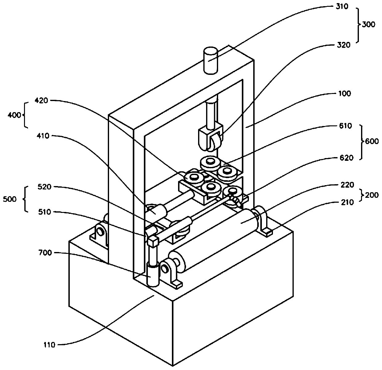
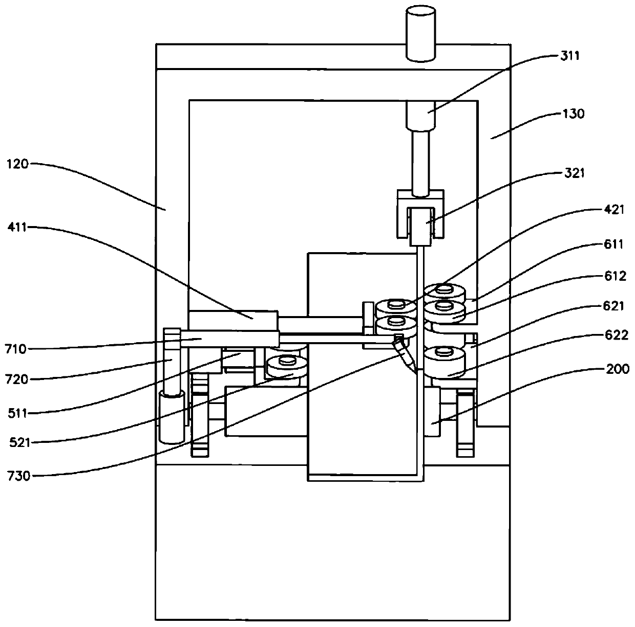
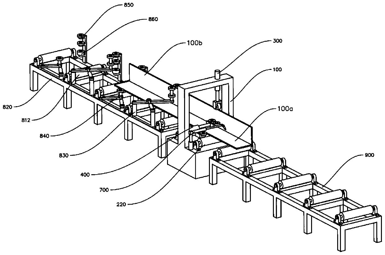
The invention discloses an assembly machine and an assembly method. Side plates and bottom plates can be respectively positioned at a fixed stop part through a second positioning structure and a thirdpositioning structure, so as to realize the clamping and positioning in the horizontal direction of the side plates of different thicknesses and the bottom plates of different widths. The first positioning structure is used to realize the clamping and positioning in the vertical direction of the side plates of different heights, so that the L-shaped steel plate can be assembled. During the assembly process, positioning of the bottom plates and the side plates in multiple directions can be realized, the offset of the bottom plate and the side plate is avoided and the assembly accuracy is effectively improved.

Description

technical field [0001] The invention relates to the field of machining, in particular to an assembly machine and an assembly method. Background technique [0002] The existing assembling machine is generally used to assemble H-shaped steel plate and T-shaped steel plate. The side plate is placed in the center of the bottom plate, and the H-shaped steel plate or T-shaped steel plate is clamped and positioned through the expansion and contraction clamping devices on both sides. . With the continuous change of production demand, different types of steel plates have appeared, such as L-shaped steel plates. However, since the side plates of the L-shaped steel plates need to be placed on one side of the bottom plate, if the L-shaped steel plates are tightened by the expansion and contraction clamping devices on both sides Clamping and positioning will cause the bottom plate and the side plate to move with each other, which is not conducive to the assembly of L-shaped steel plates...

Claims


Application Information

Patent Timeline
Patent Type & Authority Applications(China)
IPC IPC(8): B23K31/02B23K37/00B23K37/04B23K37/02
CPCB23K31/02B23K37/00B23K37/0435B23K37/0252
Inventor 佘文壮王占奎杨威邱垂金冯清川谢成利
Owner CHINA CONSTR STEEL STRUCTURE ENG CO LTD
Why Eureka
Try Eureka