Square tube splicing device

An assembly device and square tube technology, applied in auxiliary devices, transportation and packaging, conveyors, etc., can solve the problem of accuracy, pre-assembly state maintenance, positioning accuracy affecting the quality of finished products, high automation requirements, and unstable assembly In order to achieve the effect of saving manpower, reducing the difficulty of operation and meeting the needs of automatic production

Pending Publication Date: 2020-07-24
苏州光彩钢板仓有限公司
View PDF0 Cites 0 Cited by
  • Summary
  • Abstract
  • Description
  • Claims
  • Application Information

AI Technical Summary

Problems solved by technology

In the face of various construction needs, there are situations where two or more square pipes need to be spliced ​​together, especially when splicing obliquely, such as Figure 8 As shown, the two square tubes are leaning together, and the splicing part is a meeting line instead of a surface. The instability of the assembly directly increases the difficulty of subsequent welding and affects the splicing quality.
[0003] At present, there is no equipment on the market that can realize the assembly of square tubes in the above-mentioned way, and the form of automated production is becoming more and more common. A series of actions such as material, pre-splicing, conveying, and welding have high requirements on the degree of mechanical automation. The accuracy of circulation actions, the degree of maintenance of pre-assembled state, and positioning accuracy will all affect the quality of finished products and increase the difficulty of research and development.

Method used


Image

  • Square tube splicing device
  • Square tube splicing device
  • Square tube splicing device

Examples


Embodiment Construction

[0030] The technical solutions of the present invention will be clearly and completely described below in conjunction with the accompanying drawings.

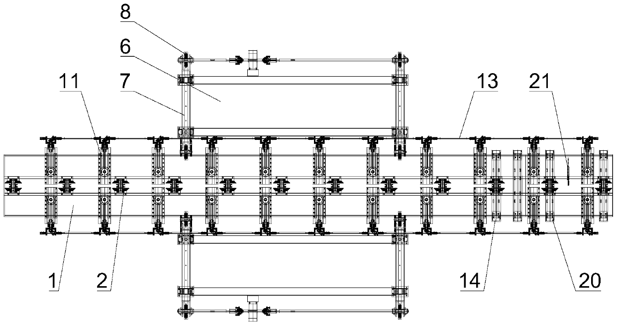
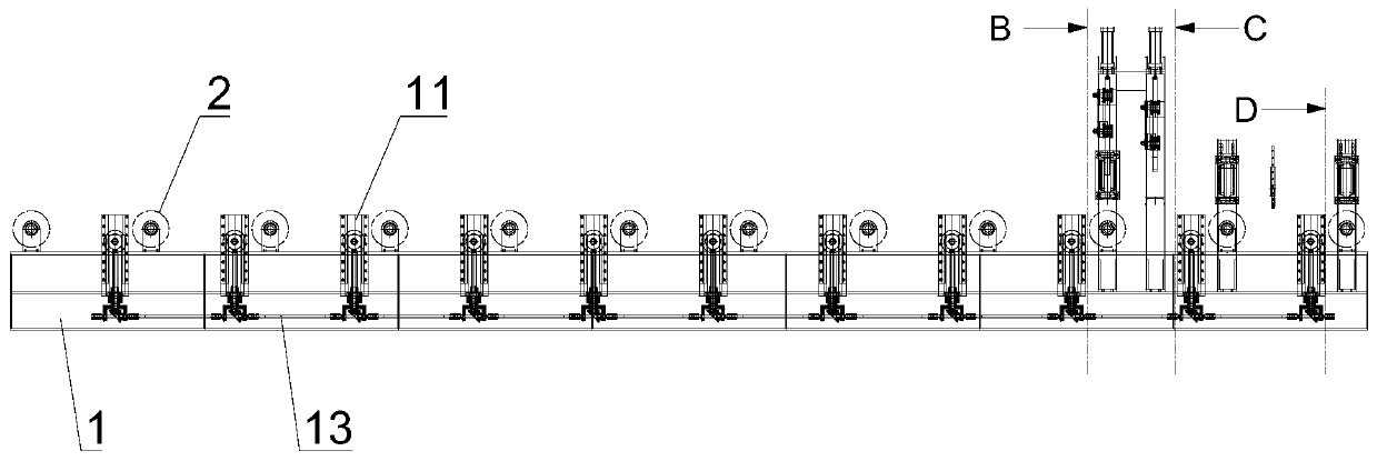
[0031] see Figures 1 to 7 As shown, this embodiment provides a square tube assembling device, which is used for splicing two square tubes in an "L" shape. Of course, it can also be an oblique assembling form at other angles, and only needs to adjust the arrangement angle of each component adaptively.

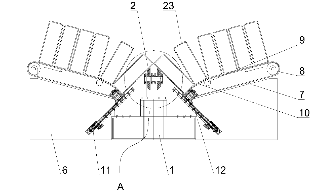
[0032] The device includes a support seat 1, a feeding mechanism, a pre-assembly mechanism, a limit mechanism and a welding mechanism.

[0033] The support base 1 is provided with conveying rollers, and several conveying rollers are arranged at intervals along the length direction of the support base 1 to form a production conveying line. The conveying roller includes two tapered surface wheels 2 inclined on both sides, a drive shaft 3, a drive wheel 4 and a mounting frame 5. The drive wheel 4 and the two tapered wheels 2 are r...


PUM


Abstract

The invention discloses a square tube splicing device. The device is used for L-shaped splicing of two square tubes. The device comprises a supporting base, a feeding mechanism, a pre-splicing mechanism, a limiting mechanism and a welding mechanism. A plurality of conveying rollers are arranged on the supporting base. The multiple conveying rollers are arranged at intervals in the length directionof the supporting base to form a production conveyor line. The feeding mechanism comprises square tube feeding tables located at the two sides of the supporting base. The square tube feeding tables on the two sides convey square tubes to the supporting base in the middle. The pre-splicing mechanism comprises guiding assemblies located at the two sides of the supporting base. Each guiding assemblycomprises a guiding wheel located at the conveying tail end of the corresponding square tube feeding table. Each conveying roller comprises two conical wheels with the conical surfaces inclined to the two sides. When the bottom surfaces of the square tubes at the two sides are supported by the corresponding guiding wheels, and the inner side surfaces are closely attached to the conical surfaces of the corresponding conical wheels, the square tubes at the two sides are in the spliced state. The limiting mechanism is located behind the pre-splicing mechanism and used for calibrating and maintaining the spliced state of the two square tubes. The welding mechanism is located behind the limiting mechanism and comprises welding guns arranged at the spliced position of the two square tubes in the spliced state.

Description

technical field [0001] The invention relates to the technical field of section steel assembly, in particular to a square pipe assembly device. Background technique [0002] Steel structure is a very important type of structure in modern buildings. It has many advantages such as high strength, light weight, good rigidity, and strong toughness, and is widely used. In the face of various construction needs, there are situations where two or more square pipes need to be spliced ​​together, especially when splicing obliquely, such as Figure 8 As shown, the two square tubes are leaning together, and the splicing part is a meeting line instead of a surface. The instability of the assembly directly increases the difficulty of subsequent welding and affects the splicing quality. [0003] At present, there is no equipment on the market that can realize the assembly of square tubes in the above-mentioned way, and the form of automated production is becoming more and more common. A se...

Claims


Application Information

Patent Timeline
Patent Type & Authority Applications(China)
IPC IPC(8): B23K31/02B23K37/00B23K37/04B65G23/04
CPCB23K31/02B23K37/00B23K37/0435B65G23/04
Inventor 易书云易仕桂陆照俊周越华殷科
Owner 苏州光彩钢板仓有限公司
Why Eureka
Try Eureka