

Thin film precise slitting device for thin-film capacitor processing
A film capacitor and film technology, which is applied in the field of film precision slitting devices for film capacitor processing, can solve the problems of labor consumption and low efficiency, and achieve the effects of fast adjustment speed, high efficiency and stable cutting
- Summary
- Abstract
- Description
- Claims
- Application Information
AI Technical Summary
Problems solved by technology
Method used
Image

Examples
Embodiment 1
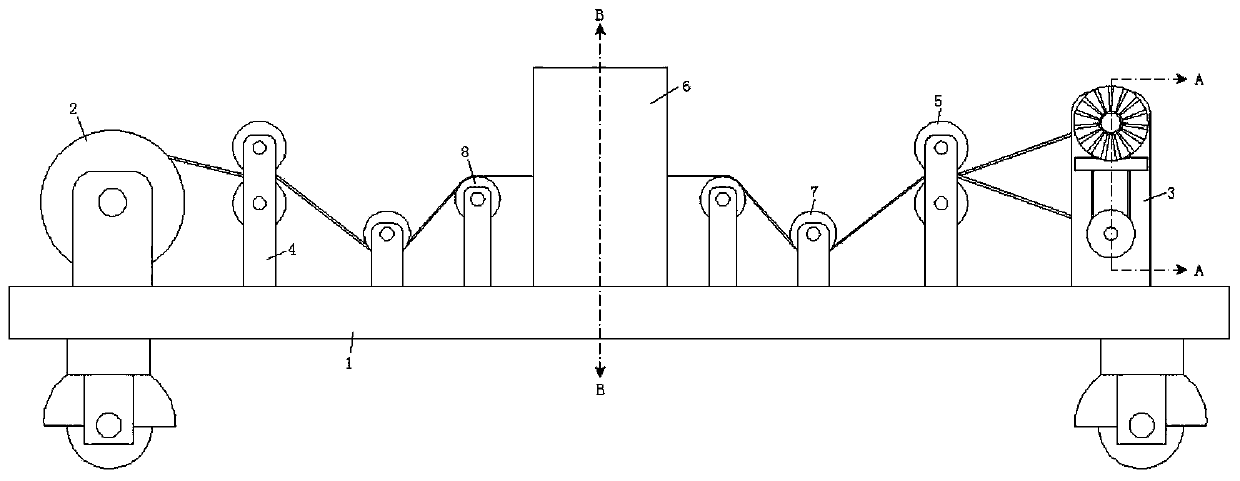
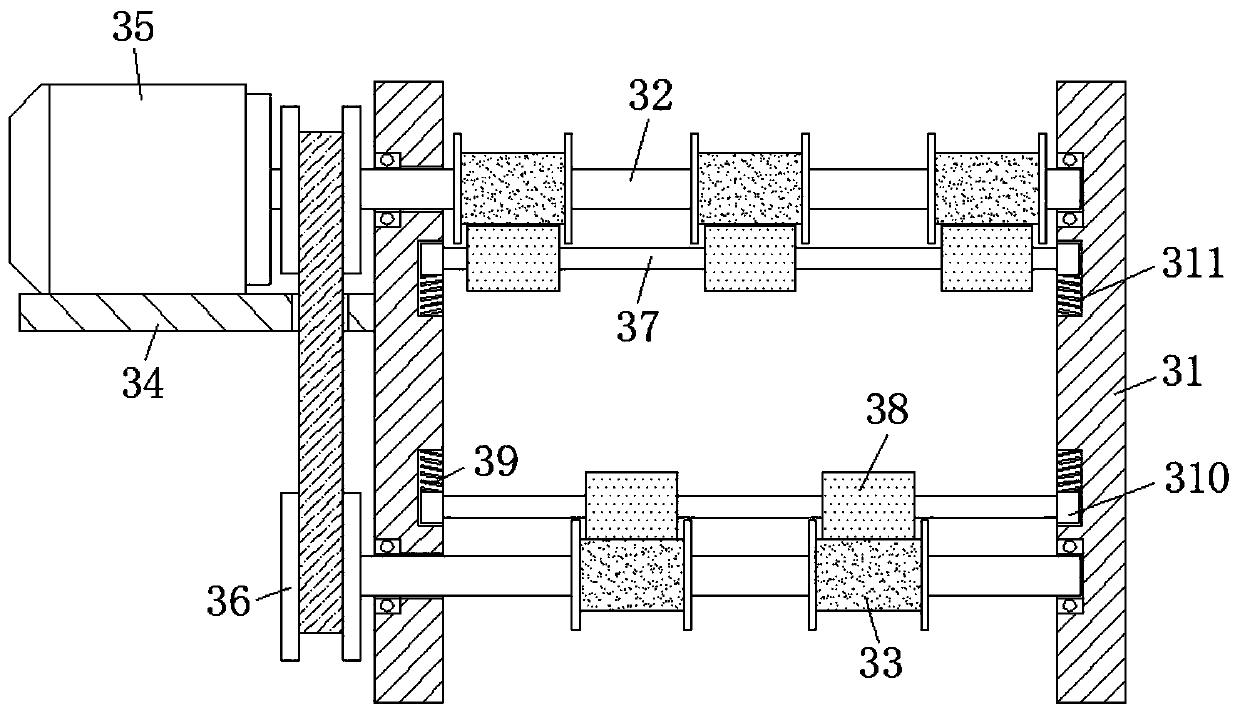
[0028] refer to Figure 1-4 , a film precision cutting device for film capacitor processing, including a base 1, universal wheels are installed at the four corners of the lower end surface of the base 1, and a pay-off roller 2 and a winding mechanism are fixedly connected to both sides of the upper end surface of the base 1 3. The winding mechanism 3 includes a mounting seat 31, and a mounting rod 32 is rotatably connected between the two mounting seats 31 through a rolling bearing. Also be connected with horizontal plate 34, the upper end of horizontal plate 34 is fixedly connected with servomotor one 35 by screw, and the rear end of two installation rods 32 all passes mounting seat one 31 and is connected by conveyor belt 36 rotations, and servomotor one 35 The output end and the upper mounting rod 32 are connected by screws, and the two mounting rods 32 are provided with a pressure rod 37 at one end close to each other. There is a mounting block 39, and a mounting groove 3...
Embodiment 2
[0032] Such as figure 1 As shown, this embodiment is basically the same as Embodiment 1. Preferably, both sides of the cutting mechanism 6 are provided with a pinch roller 1 7 and a pinch roller 2 8, and the pinch roller 2 8 is located away from the slitting mechanism 6 On one side, the height of the pinch roller two 8 is lower than the height of the pinch roller one 7 .
[0033] In this embodiment, the pressure roller one 7 and the pressure roller two 8 are arranged on both sides of the cutting mechanism 6, and the height of the pressure roller two 8 is lower than the height of the pressure roller one 7, so that the capacitor Both sides of the film are pressed tightly to ensure more stability when cutting the capacitor film, thereby ensuring the cutting quality of the capacitor film.
Embodiment 3
[0035] Such as figure 1 with 2 As shown, this embodiment is basically the same as Embodiment 1. Preferably, two mounting seats 31 are provided and symmetrically distributed on the front and rear sides of the base 1, and the mounting seats 31 are all welded on the upper end surface of the base 1, and the mounting rod 32 is provided with two and is symmetrically distributed in the upper and lower end positions of mounting seat one 31.
[0036] There are multiple winding discs 33, and the winding discs 33 on the two installation rods 32 are arranged in a staggered manner. The pressure rollers 38 are all provided with multiple winding discs 33 near the center of the mounting seat 31, and the pressure rollers The outer wall of the wheel 38 is all bonded to the outer wall of the winding disc 33, and the upper and lower ends of the horizontal plate 34 also run through a through hole, and the conveyor belt 36 is placed in the through hole, and the extruding spring 311 is all located ...
PUM
 Abstract
Description
Claims
Application Information