
Edge banding machine

An edge banding machine and edge banding technology, applied in multi-purpose machinery, mechanical surface treatment, forming/shaping machine, etc., can solve the problems affecting the quality of the sheet, and achieve the effect of ensuring stability and avoiding scratches

Pending Publication Date: 2020-07-24
广东龙德创展科技有限公司
View PDF0 Cites 5 Cited by
  • Summary
  • Abstract
  • Description
  • Claims
  • Application Information

AI Technical Summary

Problems solved by technology

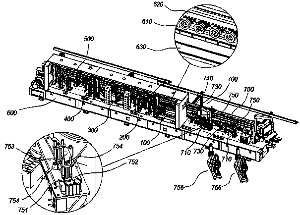
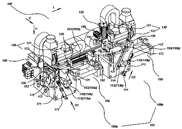
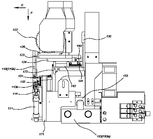
[0006] The embodiment of the present application provides an edge banding machine, which avoids leaving scratches on the side of the plate when cutting the edge banding strip, and solves the technical problem that the 45° cutting angle of the head-aligning device of the existing edge banding machine affects the quality of the plate

Method used


Image

  • Edge banding machine
  • Edge banding machine
  • Edge banding machine

Examples


Embodiment Construction

[0043] Embodiments of the present invention are described in detail below, examples of which are shown in the drawings, wherein the same or similar reference numerals denote the same or similar elements or elements having the same or similar functions throughout. The embodiments described below by referring to the figures are exemplary only for explaining the present invention and should not be construed as limiting the present invention.

[0044]In describing the present invention, it should be understood that the terms "center", "longitudinal", "transverse", "length", "width", "thickness", "upper", "lower", "front", " Orientation indicated by rear, left, right, vertical, horizontal, top, bottom, inside, outside, clockwise, counterclockwise, etc. The positional relationship is based on the orientation or positional relationship shown in the drawings, which is only for the convenience of describing the present invention and simplifying the description, rather than indicating o...


PUM


Abstract

The invention discloses an edge bonding machine. The edge bonding machine comprises an flushing device, the flushing device comprises a flushing support and a flushing assembly, the flushing assemblyis connected with the flushing support; the flushing assembly comprises a cutting assembly, a moving assembly, a flush feed driving part, a saw blade reset part and a backup plate; the cutting assembly is used for carrying out cutting on the end of a edge banding belt; the moving assembly is used for driving the flushing head assembly to do reciprocating motion in the conveying direction L of theplates; the flush feed driving part is connected with the cutting assembly to drive the cutting assembly to move to a cutting position; the saw blade reset part is connected with the moving assembly and the flush feed driving part so as to drive the cutting assembly to move so that cutting the end of the edge banding belt can be carried out; and the backup plate is movably connected with the moving assembly so as to abut against the plates during cutting and avoid the plates after cutting is completed. According to the edge banding machine of the embodiment, scratches are prevented from beingleft on the side faces of the plates when edge banding strips are cut, and the technical problem that the quality of the plates is affected due to 45-degree oblique cutting of an existing flushing device is solved.

Description

technical field [0001] The invention belongs to the technical field of plate edge banding, and in particular relates to an edge banding machine. Background technique [0002] In the process of furniture production, it is necessary to use an edge banding machine to seal the outer edge of the board to improve the performance of the board. After the edge banding treatment, edge bands will be reserved at both ends of the plate, and the plate needs to be processed with an edge banding machine to cut both ends of the edge banding, so that the edge banding and the two ends of the plate completely flush. [0003] In the prior art, the edge banding machine is equipped with a head-to-head device for head-to-head processing. In the current conventional edge-banding machine, the head-to-head device adopts a 45° oblique cutting method for cutting, that is, the plate is conveyed along the horizontal direction, and the head-to-head device The cutting movement direction of the machine is ...

Claims


Application Information

Patent Timeline
IPC IPC(8): B27N7/00B27B5/04B27B5/29B27C9/04B27M1/00B27C5/02
CPCB27N7/00B27B5/04B27B5/29B27C9/04B27M1/003B27C5/02
Inventor 欧阳展图
Owner 广东龙德创展科技有限公司
Learn More