Film blowing machine for producing POF heat shrinkable film

A technology of heat shrinkable film and film blowing machine, which is applied in the direction of cleaning methods and utensils, cleaning hollow objects, chemical instruments and methods, etc., which can solve the problem of dirt contamination, the inability to adjust the wind direction of a single air outlet according to demand, and unfavorable use of heat shrinkable film, etc. problem, to achieve the effect of easy cleaning

Inactive Publication Date: 2020-07-24
浙江九腾包装材料有限公司
View PDF0 Cites 2 Cited by
  • Summary
  • Abstract
  • Description
  • Claims
  • Application Information

AI Technical Summary

Problems solved by technology

[0003] However, when using a film blowing machine for heat shrinkable film production, the fan is used for heat dissipation and shaping, but because the opening of the fan is upward, it is easy to contaminate some dirt on the air outlet of the fan, so that when the heat shrinkable film is produced, the fan The dirt at the air outlet will rush to the heat-shrinkable film together with the wind blown by the fan to the heat-shrinkable film, so that the heat-shrinkable film will be contaminated with dirt, which is not conducive to the use of the heat-shrinkable film; The wind direction of multiple air outlets is generally adjusted together, and the wind direction of a single air outlet cannot be adjusted according to the demand, so that the customer's needs cannot be well met

Method used


Image

  • Film blowing machine for producing POF heat shrinkable film
  • Film blowing machine for producing POF heat shrinkable film
  • Film blowing machine for producing POF heat shrinkable film

Examples


Embodiment Construction

[0020] In order to make it easy to understand the technical means, creative features, goals and effects achieved by the present invention, the present invention will be further explained below in conjunction with specific embodiments.

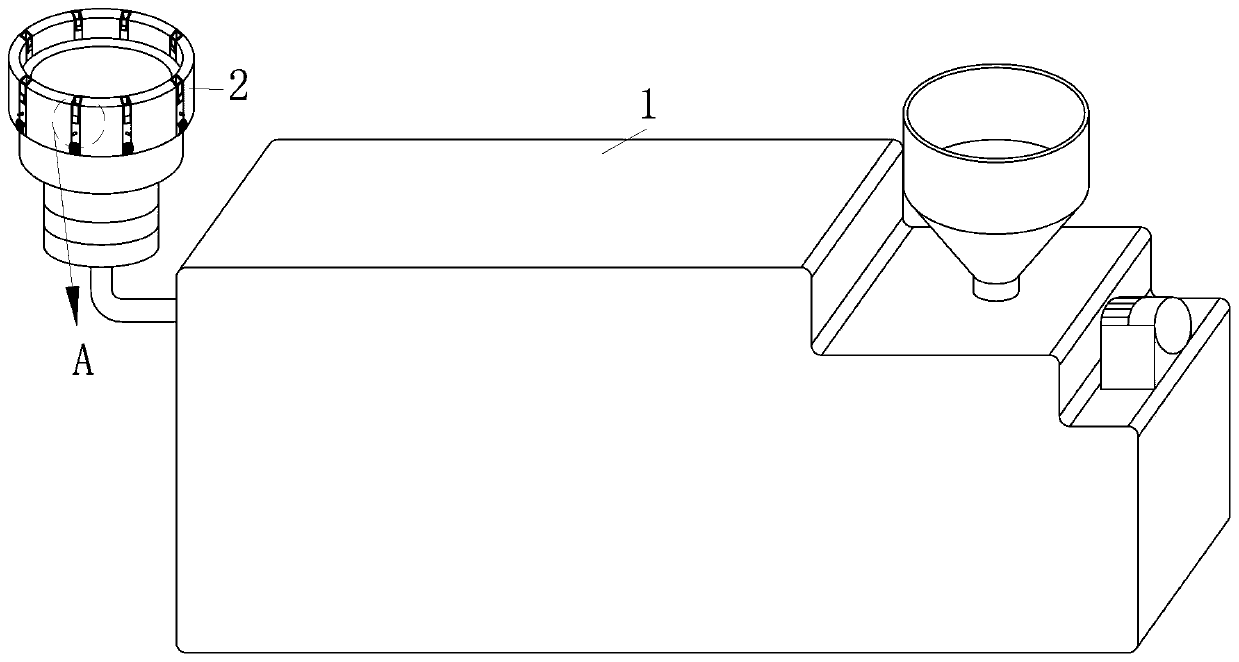
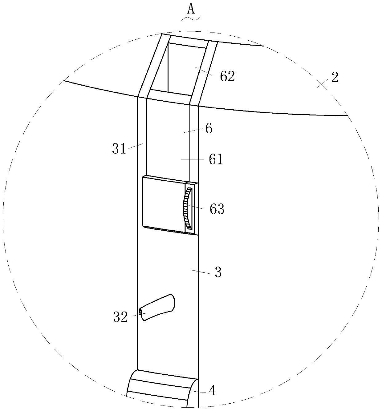
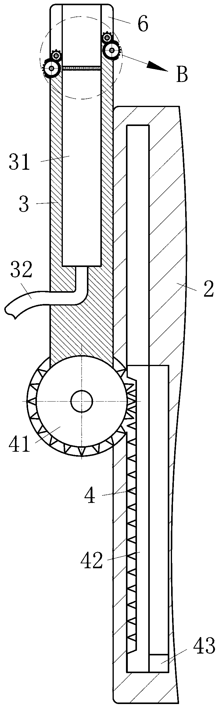
[0021] Such as Figure 1-Figure 5 As shown, a film blowing machine for producing POF heat shrinkable film according to the present invention includes a film blowing machine body 1, a casing 2, an air outlet mechanism 3, a rotating mechanism 4, a driving mechanism 5 and an adjusting mechanism 6. , The film blowing machine body 1 for producing heat shrinkable film is installed with the housing 2 for fixing, and the rotating mechanism 4 for rotating is installed on the housing 2 for fixing, for cooling The air outlet mechanism 3 is fixedly connected to the rotating mechanism 4 for rotation, and the air outlet mechanism 3 for cooling is rotatably connected to the housing 2 for fixing. The driving mechanism 5 is installed in the housing 2 for fixing, ...


PUM


Abstract

The invention relates to the field of heat shrinkable film production, in particular to a film blowing machine for producing a POF heat shrinkable film. The machine comprises a film blowing machine body, a housing, an air outlet mechanism, a rotating mechanism, a driving mechanism and an adjusting mechanism. The rotating mechanism is installed on the air outlet mechanism. The rotating mechanism isengaged with the driving mechanism, and the angle between the air outlet mechanism and the housing is adjusted through the cooperation of the driving mechanism and the rotating mechanism, so that theair outlet mechanism blows first in the direction away from the center of the housing to clean up the dirt accumulated in the air outlet mechanism, the dirt is prevented from a heat shrinkable film when the air outlet mechanism is used to cool the heat shrinkable film, and the heat shrinkable film production is benefited. The adjusting mechanism is installed on the air outlet mechanism, the winddirection of the air outlet mechanism is adjusted through the adjusting mechanism, so that the cooling of the heat shrinkable film under different occasions is convenient to meet, and different needsof customers are satisfied.

Description

Technical field [0001] The invention relates to the field of heat shrinkable film production, in particular to a blown film machine for producing POF heat shrinkable film. Background technique [0002] Heat shrinkable film is used for the sales and transportation of various products, and its main function is to stabilize, cover and protect the product. The shrink film must have high puncture resistance, good shrinkage and a certain shrinkage stress. During the shrinking process, the film cannot produce holes. Since shrink film is often used outdoors, it is necessary to add UV anti-ultraviolet agent. Heat shrinkable film is widely used in the outer packaging of various products such as food, medicine, sterilized tableware, stationery and sports goods, craft gifts, printed matter, hardware and plastic products, telephones, electronic appliances, etc., especially in irregularly shaped items or commodities. Combined (cluster) packaging can not only meet the functions of moisture-p...

Claims


Application Information

Patent Timeline
Patent Type & Authority Applications(China)
IPC IPC(8): B29C55/28B29C35/16B08B9/032
CPCB08B9/0328B29C35/16B29C55/28B29C2035/1658
Inventor 金治平
Owner 浙江九腾包装材料有限公司
Why Eureka
Try Eureka