Material conveying device provided with screw shaft spreading mechanism as well as material conveying channel

A conveying device and conveying channel technology, which is applied in the field of material drying equipment, can solve the problems of material adhesion, material accumulation, and easy adhesion of materials to the board wall, and achieve the effect of preventing wall hanging.

Pending Publication Date: 2020-07-24
AMCON FUJIAN ENVIRONMENT PROTECTION EQUIP CO LTD
View PDF1 Cites 6 Cited by
  • Summary
  • Abstract
  • Description
  • Claims
  • Application Information

AI Technical Summary

Problems solved by technology

The inventor found that the device has the following disadvantages during use: 1. After the screw shaft material spreading device has finished spreading the material, it will enter the bottom of the material rolling device. The rolling guide plate on the device side cannot fall off
2. The material blocking device only plays the role of blocking material, but if the material is fed too quickly, the material will accumulate on the top of the material blocking device and eventually fall out of the conveying platform
However, if the baffle is used to extend the side wall of the channel, the material is easy to adhere to the wall, resulting in poor feeding and spreading
3. The helical blade at the end of the screw shaft is too close to the edge of the conveying platform, which will easily cause the accumulation of materials on the edge when spreading the material, and more likely to cause the accumulation of materials on the edge after entering the material rolling device

Method used


Image

  • Material conveying device provided with screw shaft spreading mechanism as well as material conveying channel

Examples


no. 1 example

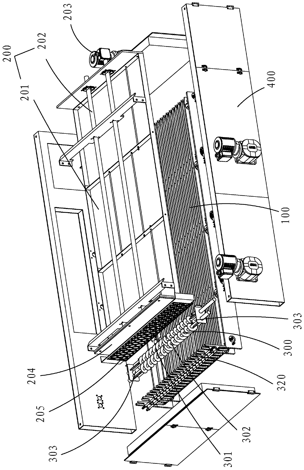
[0024] Such as figure 1 As shown, a material conveying device with a spiral shaft material spreading mechanism includes a stacked strip push-type material conveying platform 100, a spiral shaft material spreading mechanism 300 located above the beginning of the conveying platform 100, and the spiral shaft material spreading mechanism 300. The material rolling device 200 is provided above the conveying platform 100 on one side of the mechanism 300 toward the material conveying direction.

[0025] The driving method of the conveying platform 100 is the same as that of the stacked push-type material conveying platform of Chinese invention 201911093469.3 (hereinafter referred to as "comparison document"). The first motor 101 drives the conveying platform 100 to perform a reciprocating synchronous circular motion to carry and propel the material forward;

[0026] The material rolling device 200 includes: a rolling platform 201 and a rolling driving mechanism 202 . The specific wo...

no. 2 example

[0037] As another embodiment of the present invention: a material conveying channel for conveying materials from top to bottom, comprising at least two side walls facing each other; wherein at least one side wall is formed by stacking two groups of grid bar assemblies alternately. As a result, at least one group of grid bar components performs reciprocating synchronous circular motion. The specific structure and working principle of the side wall composed of the grid bar assembly in this embodiment are the same as those of the stacked bar push-type material conveying platform in the reference document. Due to the reciprocating movement of the bars, such a material conveying channel prevents material from accumulating on the side walls. It can also be, wherein at least one side wall is two boards arranged in parallel and close to each other, one board close to the material is a hollow board, and the other board is a sealing board, and the hollow board or the sealing board is re...


PUM


Abstract

The invention provides a material conveying device provided with a screw shaft spreading mechanism. The material conveying device comprises a fold pushing type material conveying platform, the screw shaft spreading mechanism arranged above the starting end of the conveying platform and a material grinding device arranged above the conveying platform; a first motor drives a first driving mechanismto drive the conveying platform to perform reciprocating synchronous circumferential motion; the material grinding device comprises a grinding platform and a second driving mechanism; a second motor drives the second driving mechanism to drive the grinding platform to perform reciprocating synchronous circumferential motion vertical to the pushing direction of a material; the starting end of the conveying platform is upwarped, exceeds height of a screw shaft, and forms a material conveying channel from top to bottom with side walls of the material grinding device; and a hollow-out plate is arranged on the side wall of one side of the material grinding device and attached to the side wall. The side wall formed by grid strips and the side wall of the material grinding device form relative displacement with the tightly attached hollow-out plate, and material adhesion and accumulation on the side wall of the material conveying channel can be prevented.

Description

【Technical field】 [0001] The invention belongs to the technical field of material drying equipment, and in particular relates to a material conveying device with a screw shaft spreading mechanism and a material conveying channel. 【Background technique】 [0002] In the process of solid-liquid separation and solid medicament brewing, a hopper is often used for temporary storage and preparation for feeding when feeding materials, but some viscous and easy-to-harden materials are easy to adhere to the side wall of the hopper or An overhead structure is formed through the support of the side walls, so that the materials cannot be pushed and conveyed from top to bottom. [0003] In addition, the material drying equipment is widely used in the drying process of chemical industry, food, medicine, building materials and other industries. In the field of sludge treatment, the mud cake produced by the sludge dewatering machine is finally discharged into a material with a lower moistur...

Claims


Application Information

Patent Timeline
Patent Type & Authority Applications(China)
IPC IPC(8): B65G69/04B65D88/64B65G69/14
CPCB65D88/64B65G69/0433B65G69/14
Inventor 郑朝志
Owner AMCON FUJIAN ENVIRONMENT PROTECTION EQUIP CO LTD
Why Eureka
Try Eureka