
Automatic ceramic thermal spraying device

A thermal spraying and ceramic technology, applied in coating, melting spraying, metal material coating process, etc., can solve the problems of no cooling function and low workpiece processing efficiency, and achieve a sufficient scope of action, improved processing efficiency, and convenient The effect of disassembling the workpiece

Pending Publication Date: 2020-07-24
翰贝摩尔表面技术(江苏)有限公司
View PDF0 Cites 1 Cited by
  • Summary
  • Abstract
  • Description
  • Claims
  • Application Information

AI Technical Summary

Problems solved by technology

[0003] The existing ceramic thermal spraying equipment generally does not have a cooling function, and the processing efficiency of the workpiece is low, which needs to be further improved

Method used


Image

  • Automatic ceramic thermal spraying device
  • Automatic ceramic thermal spraying device
  • Automatic ceramic thermal spraying device

Examples


Embodiment Construction

[0023] The technical solutions of the present invention will be described below in conjunction with the accompanying drawings and embodiments.

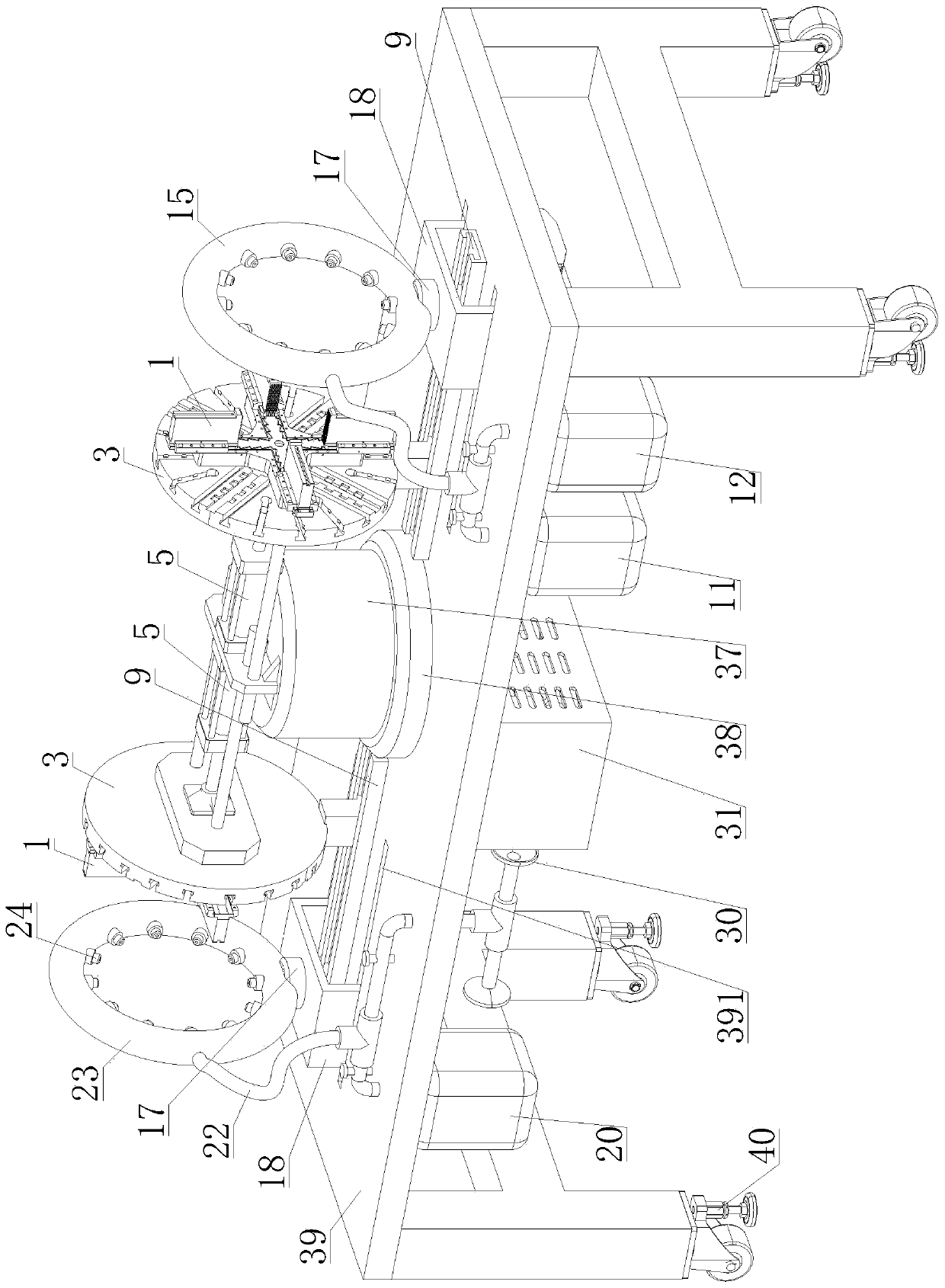
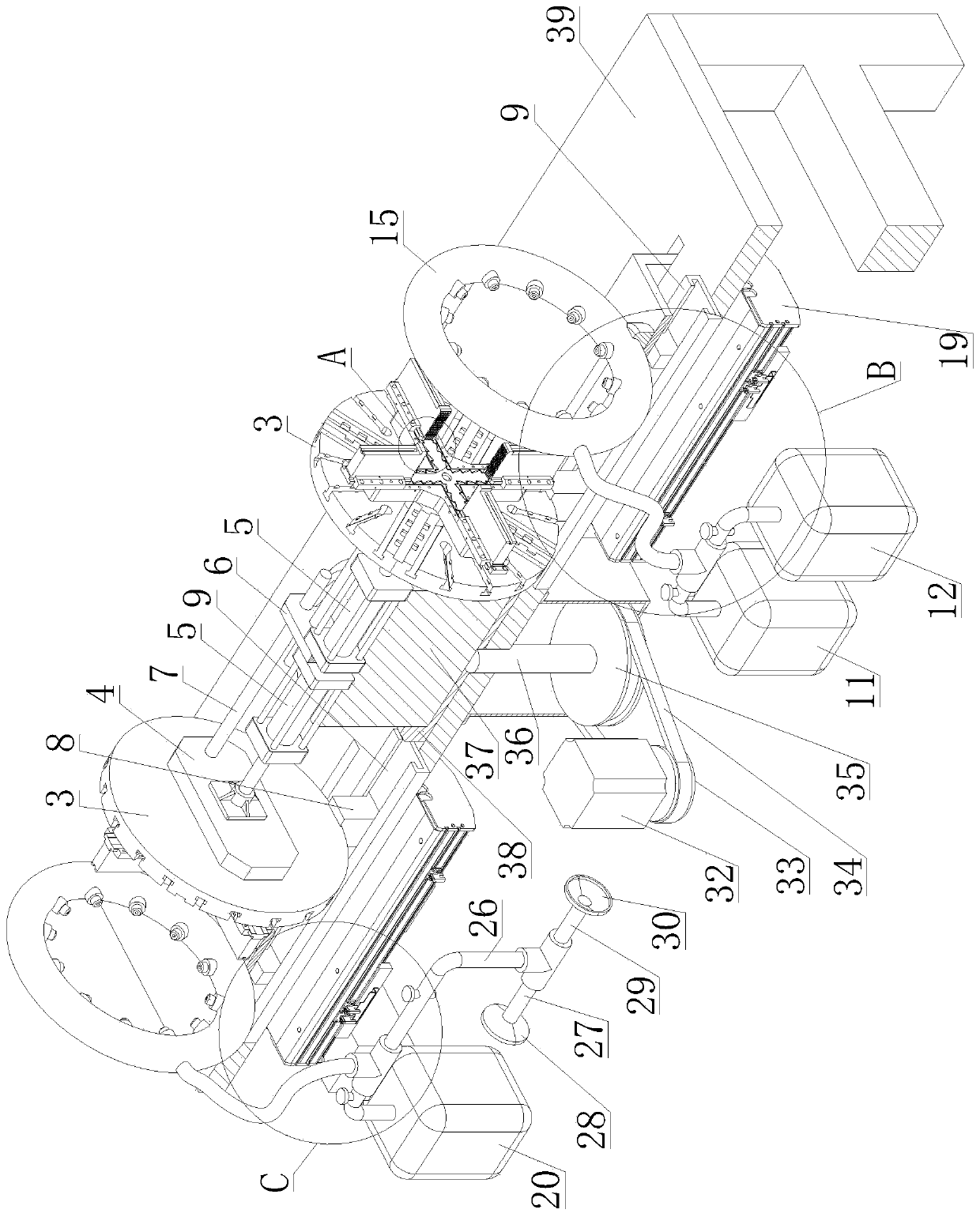
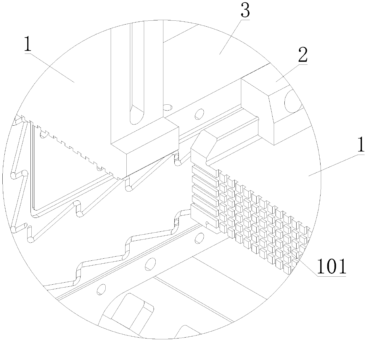
[0024] Such as Figure 1 to Figure 5 As shown, a kind of automatic ceramic thermal spraying equipment described in the present invention includes a clamping mechanism, a raw material tank 11, a first connecting pipe 111, an oxygen tank 12, a second connecting pipe 121, a first three-way pipe 13, a third Connecting pipe 14, first annular pipe 15, spray gun 16, second annular pipe 23, spray nozzle 24, mobile drive mechanism, blowing mechanism, turntable 37 and frame 39;

[0025] The raw material tank 11 and the oxygen tank 12 are all arranged on the frame 39, the raw material tank 11 communicates with the first three-way pipe 13 through the first connecting pipe 111, and the oxygen tank 12 communicates with the first three-way pipe 13 through the second connecting pipe 121 The two ends of the third connecting pipe 14 communicate with t...


PUM


Abstract

The invention provides an automatic ceramic thermal spraying device which comprises clamping mechanisms, a raw material tank, a first connecting pipe, an oxygen tank, a second connecting pipe, a firstthree-way pipe, a third connecting pipe, a first annular pipe, spraying guns, a second annular pipe, spraying nozzles, movable driving mechanisms, an air blowing mechanism, a rotating table and a machine frame. The raw material tank communicates with the first three-way pipe through the first connecting pipe. The oxygen tank communicates with the first three-way pipe through the second connectingpipe. The two ends of the third connecting pipe communicate with the first three-way pipe and the first annular pipe correspondingly. The output end of the air blowing mechanism communicates with thesecond annular pipe. Each movable driving mechanism comprises an installing table, an installing frame and a linear guide rail. A driving device for driving the rotating table to rotate is arranged on the machine frame. Cylinders for driving installing plates to transversely move are arranged on the rotating table. By means of the automatic ceramic thermal spraying device, two workpieces can be processed at a time, the two workpieces are at a thermal spraying state and a cooling state correspondingly, the workpiece processing efficiency is improved, and the workpieces can be conveniently detached and assembled.

Description

technical field [0001] The invention relates to the technical field of thermal spraying equipment, in particular to an automatic ceramic thermal spraying equipment. Background technique [0002] Thermal spraying refers to the process of depositing fine and dispersed metallic or non-metallic coating materials on the surface of a prepared substrate in a molten or semi-molten state in a series of processes to form a certain spray deposition layer. It uses a heat source to heat powdery or filamentary metal or non-metallic materials to a molten or semi-molten state, and then sprays them on the surface of the pretreated substrate at a certain speed by means of the flame itself or compressed air, and deposits them to form a A technology for surface coatings with various functions. [0003] The existing ceramic thermal spraying equipment generally does not have a cooling function, and the processing efficiency for the workpiece is low, which needs to be further improved. Contents...

Claims


Application Information

Patent Timeline
Patent Type & Authority Applications(China)
IPC IPC(8): C23C4/12C23C4/04
CPCC23C4/12C23C4/04
Inventor 朱秋日
Owner 翰贝摩尔表面技术(江苏)有限公司
Learn More