Adjustable fixed plate and hanging fixture

A fixed plate, adjustable technology, applied in the direction of electrical components, electrolysis process, printed circuit manufacturing, etc., can solve the problem of poor conduction at the movable jaw

Pending Publication Date: 2020-07-24
KUNSHAN DONGWEI MACHINERY CO LTD
View PDF1 Cites 5 Cited by
  • Summary
  • Abstract
  • Description
  • Claims
  • Application Information

AI Technical Summary

Problems solved by technology

[0006] Therefore, the technical problem to be solved by the present invention i

Method used


Image

  • Adjustable fixed plate and hanging fixture
  • Adjustable fixed plate and hanging fixture
  • Adjustable fixed plate and hanging fixture

Examples


Embodiment 1

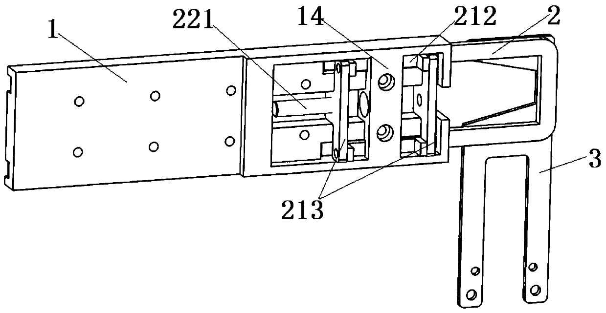
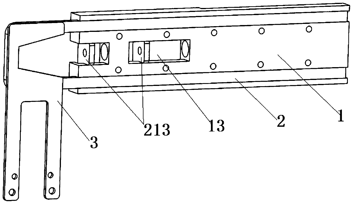
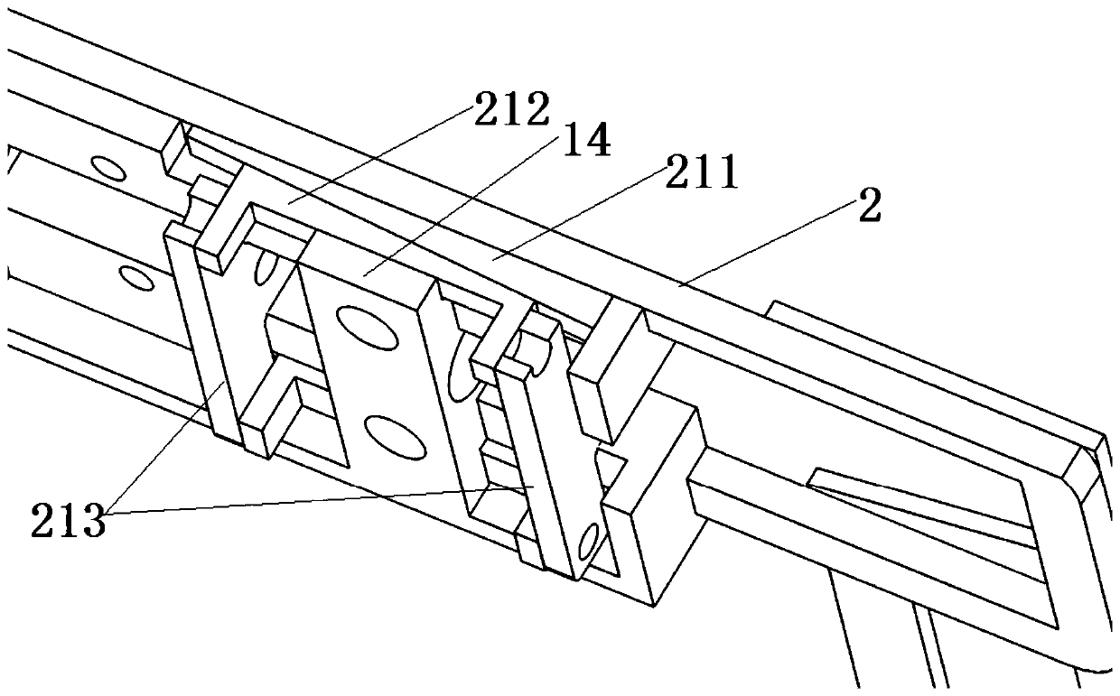
[0052] This embodiment provides an adjustable fixed plate, such as Figure 1 to Figure 6 As shown, it is suitable to be fixed on the bottom of the conductive plate 4, and a fixed jaw 5 is connected to the bottom of the conductive plate 4. The adjustable fixed plate includes a body 1, a conductive slide bar 2 and a locking mechanism.

[0053] Wherein, the body 1 is arranged on the conductive plate 4; the conductive slider 2 is slidably arranged between the body 1 and the conductive plate 4, and one side of the conductive slider 2 is connected with a sliding jaw 6, and the sliding jaw 6 is connected to the conductive plate 4. The conductive sliding bar 2 is conductively connected; the locking mechanism has a pressing structure arranged between the body and the conductive sliding bar to press the conductive sliding bar 2 on the conductive plate 4 .

[0054] With the adjustable fixed plate of this structure, the conductive slide bar 2 can slide outward between the main body 1 and ...

Embodiment 2

[0082] This embodiment provides a hanger, such as Figure 7 As shown, it includes two sets of adjustable fixed plates and conductive plates 4 in Embodiment 1.

[0083] The adjustable fixed plate is arranged on the lower part of the conductive plate 4 , and the fixed jaw 5 is arranged on the fixed plate below the adjustable plate, and the first side of the body 1 is attached to the conductive plate 4 . Two sets of adjustable fixing plates are located on opposite sides of the conductive plate 4 in the thickness direction; the two sliding jaws 6 are symmetrical about the central axis of the fixed guide plate 213 in the initial state, and slide the two conductive slide bars 2 outward or inward to Adjusting the distance between the two sliding jaws 6 can adapt to the clamping of circuit boards of different widths.

[0084] Alternatively, an adjustable fixing plate can be provided on only one side of the conductive plate 4, and the distance between the sliding jaw 6 and the fixed j...


PUM


Abstract

The invention provides an adjustable fixed plate and a hanging fixture. The adjstable fixed plate comprises a main body, a conductive slide rod and a locking mechanism. The hanging fixture comprises the adjustable fixed plate. The main body is arranged on a conductive plate; the conductive slide rod is slidably arranged between the main body and the conductive plate; sliding clamping jaws are connected to one side of the condutive slide rod; and the locking mechanism is provided with an extrusion structure arranged between the main body and the conductive slide rod so as to tightly press the conductive slide rod onto the conductive plate. Acording to the adjustable fixed plate with the structure, the sliding clamping jaws can adapt to clamping circuit boards with different widths; the conductive slide rod is tightly pressed on the condutive plate through the extrusion structure, and the conductive slide rod is tightly pressed on the condutive plate through an extrusion way so as to bepositioned, so that the contact area of the extrusion structure and the conductive slide rod is large; and meanwhile, a pressing force acted on the conductive slide rod is stable, the condutive sliderod is positioned firmly through thelocking mechanism after sliding in place, and the conductive slide rod stably contacts the conductive plate so as to conduct electricity stably, so that the slidingclamping jaws can be ensured to conduct electricity stably.

Description

technical field [0001] The invention relates to the technical field of electroplating equipment, in particular to an adjustable fixing plate and a hanger. Background technique [0002] When the circuit board is electroplated through the electroplating tank, the circuit board is clamped under the hanger by multiple grippers arranged at intervals, and the conveying mechanism drives the hanger to move to drive the circuit board to perform electroplating in tanks with different functions. During electroplating, it is necessary to guide the cathode current from the conductive plate to the jaw fixing plate, and then guide the current from the jaw fixing plate to the jaws. After the jaws are charged, they are clamped on the circuit board to provide cathode electricity for the circuit board, so that the circuit board The charge reacts with the metal cations in the electroplating tank to complete the electroplating. [0003] In order to ensure the clamping stability, the two ends in...

Claims


Application Information

Patent Timeline
IPC IPC(8): C25D17/08H05K3/18
CPCC25D17/08H05K3/188
Inventor 韩友生方荣平李阳照赵改兵袁晓波
Owner KUNSHAN DONGWEI MACHINERY CO LTD
Why Eureka
Try Eureka