Prefabricated combined PE drainage channel
A drainage tank and combined technology, applied to drainage structures, waterway systems, water supply devices, etc., can solve the problems of inability to achieve sustainable utilization of material recycling, difficult maintenance, low work efficiency, etc., and achieve recyclability Increase, reduce maintenance costs, and ease of installation
- Summary
- Abstract
- Description
- Claims
- Application Information
AI Technical Summary
Problems solved by technology
Method used
Image
Examples
Embodiment 1
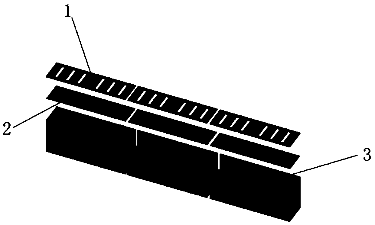
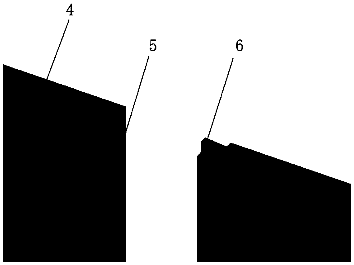
[0020] refer to Figure 1-2 , a prefabricated combined PE drainage channel, which is spliced by several individual drainage channels, and the single drainage channel includes a drainage channel cover plate 1, a drainage channel side plate, a drainage channel bottom plate, a filter mesh 2 and a support rib 3 , the side plate of the drain tank is arranged above the bottom plate of the drain tank to form a tank body with an opening facing upward, the support ribs 3 are evenly arranged in the tank body, the filter mesh 2 is arranged above the side plate of the drain tank, and the drain tank The cover plate 1 is set on the top of the filter mesh 2, the bottom plate of the drainage tank is provided with threaded holes for connecting with the drainage pipe, the top of the side plate of the drainage tank is provided with an "L" shaped notch 4, and the side of the drainage tank One of the two ends of the board is a slot 5 structure, and the other end is a tenon 6 structure, and the s...
Embodiment 2
[0022] A prefabricated combined PE drainage channel, which is spliced by several individual drainage channels, and the single drainage channel includes a drainage channel cover plate 1, a drainage channel side plate, a drainage channel bottom plate, a filter mesh 2 and a support rib 3, The side plate of the drainage tank is arranged on the top of the bottom plate of the drainage tank to form a tank body with an opening upward, the supporting ribs 3 are evenly arranged in the tank body, the filter mesh 2 is arranged above the side plate of the drainage tank, and the cover of the drainage tank The plate 1 is set above the filter mesh 2, the bottom of the side plate of the drainage tank is provided with a threaded hole for connecting with the drainage pipe, the top of the side plate of the drainage tank is provided with an "L" shaped notch 4, and the side plate of the drainage tank is provided with an "L" shaped notch 4. One end of the side plate has a slot 5 structure, and the ...
Embodiment 3
[0024] On the basis of Embodiment 1 or 2, the support rib 3 is a U-shaped structure, the opening of the support rib 3 is arranged in the tank body downward, and the top of the support rib 3 is connected to the bottom of the "L"-shaped notch 4 flush.
PUM
 Abstract
Description
Claims
Application Information
 - R&D
- Intellectual Property
- Life Sciences
- Materials
- Tech Scout
- Unparalleled Data Quality
- Higher Quality Content
- 60% Fewer Hallucinations
Browse by: Latest US Patents, China's latest patents, Technical Efficacy Thesaurus, Application Domain, Technology Topic, Popular Technical Reports.
© 2025 PatSnap. All rights reserved.Legal|Privacy policy|Modern Slavery Act Transparency Statement|Sitemap|About US| Contact US: help@patsnap.com


